
Knowledge
VAD Torch Gas Distribution Components: Drawing and Inspection Requirements
Oct
VAD Torch Gas Distribution Components determine how precursor vapors, fuel, oxygen, and carrier gases reach the reaction zone. In vapor axial deposition, small deviations in gas ring geometry, hole position, or sealing surfaces can shift flame shape, alter soot deposition symmetry, and eventually affect preform quality. Because these parts operate at high temperature and are periodically disassembled for cleaning, they also wear in ways that are not always visible during routine maintenance. This article explains what engineers and maintenance teams should specify on drawings and how to inspect incoming or reworked VAD burner gas rings and related precision torch components before they enter service.
Why VAD Gas Distribution Differs from OVD and MCVD
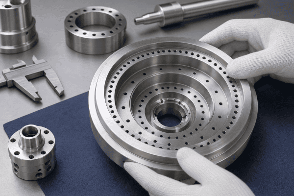
VAD, OVD, and MCVD use different deposition geometries and burner arrangements. In VAD, the torch typically directs gases toward a rotating seed rod while the preform grows axially. In OVD, deposition occurs on a rotating bait rod in a lathe-like arrangement. MCVD is a tube-based modified chemical vapor deposition process rather than an outside deposition method. These differences mean the gas distribution hardware is not interchangeable between processes.
For VAD torch gas distribution components, the variables that matter most usually include number and arrangement of gas channels or rings, hole pitch, hole diameter, and angular spacing. Concentricity between inner and outer rings is equally important because it governs how symmetrical the flame becomes as gases leave the torch face. Flatness and surface finish of sealing faces control whether channels stay isolated from one another. Mounting interface and alignment features determine how repeatably the assembly seats in the torch body. Material selection for thermal and chemical exposure rounds out the list.
- Number and arrangement of gas channels or rings
- Hole pitch, hole diameter, and angular spacing
- Concentricity between inner and outer rings
- Flatness and surface finish of sealing faces
- Mounting interface and alignment features
- Material selection for thermal and chemical exposure
The deposition torch consumables used in VAD may share general principles with VAD core deposition burner parts, but the drawing should always reflect the actual process. Do not assume that a ring set or nozzle arrangement from one process will perform the same way in another. Process engineers who treat VAD torch gas distribution components as generic hardware often discover that small geometry differences produce measurable differences in soot deposition. Similar geometry on an OVD lathe can behave differently because the torch orientation relative to the growing body is not the same, and the thermal profile around the deposition zone follows its own pattern.
Key Dimensions to Define on VAD Torch Gas Distribution Drawings
A useful drawing does more than show overall dimensions. It should define the features that control gas flow, sealing, and alignment. The following categories are common starting points for VAD burner gas rings and related precision torch components.
Gas Hole Geometry
Hole diameter, pitch, and angular position affect flow distribution. If holes are specified as a pattern, the drawing should state whether the pattern is equally spaced, whether any holes are intentionally blocked or reduced, and what reference datum establishes the first hole. On multi-ring components, the angular relationship between rings matters because it influences how gas streams interact near the torch face. For VAD torch gas distribution components, a drawing that omits the angular clocking between rings effectively leaves part of the flow field undefined.
Hole diameter tolerances deserve their own callout because a few hundredths of a millimeter can change the balance between adjacent channels. When holes are produced by drilling, reaming, or electrical discharge machining, the drawing should state the permitted process or at least a finish requirement that rules out methods incapable of holding the tolerance. Excessive burrs at hole exits disrupt the local flow field, so deburring requirements belong on the drawing rather than in a separate note that may be overlooked.
Concentricity and Runout
Concentricity between gas rings and the torch axis is often critical for flame symmetry. Runout on sealing faces can cause leaks between channels. The drawing should specify which features are functional datums and what tolerances apply. Where possible, define concentricity relative to the mounting interface rather than to an arbitrary outer diameter. When VAD torch gas distribution components are reworked or replaced, concentricity should be re-verified rather than assumed from the original inspection record. A part that has been cleaned, resurfaced, or repaired can shift its effective axis enough to change flame symmetry, even when the individual features still measure within tolerance.
Sealing Surfaces and Surface Finish
Gas distribution components often rely on metal-to-metal seals, gaskets, or elastomer seals. Surface finish, flatness, and scratch acceptance criteria should be stated for each sealing face. A surface that is too rough may leak; a surface that is too smooth may not retain a gasket properly or may be damaged during handling. The correct specification depends on the seal type and the engineering requirements of the torch.
Sealing face requirements for VAD torch gas distribution components are closely tied to the overall burner assembly. For a related discussion on dimensional checks before assembly, see VAD burner nozzle replacement dimensional and assembly checks.
Material and Heat Treatment
Material selection depends on the component’s function, temperature exposure, chemical environment, and mechanical loads. Common materials for torch components may include stainless steels, nickel alloys, or other heat-resistant alloys. The drawing should state the required material condition, any heat treatment, and any restrictions on substitutes. Do not select a material based only on a generic product category; verify it against the actual operating conditions and the equipment documentation.
Where a coating is used to extend service life or reduce oxidation, the drawing should specify the coating type, thickness range, and areas to be masked. Uncontrolled coating thickness on sealing faces changes the assembled geometry, so masking and post-coating dimensional verification belong in the specification.
Marking and Traceability
For maintenance and quality records, it helps to specify a part number, revision, and any required traceability markings. If the component will be cleaned or reworked, marking should remain legible without interfering with sealing surfaces. Traceability is especially valuable when VAD torch gas distribution components are rotated between multiple torches or operating lines.
For a broader discussion of material selection and reverse engineering, the guide on custom OVD and VAD burner sourcing provides additional context. The discussion of pressure balancing and gas flow dynamics in multi-channel OVD/VAD torches explains how channel geometry affects the balance between gas streams, which in turn informs how you specify those channels on the drawing.
Inspection Requirements for Incoming VAD Gas Distribution Components
Inspection should confirm that the component matches the drawing and is suitable for service. The exact inspection plan depends on the part’s function, but the following checks are commonly relevant for VAD burner gas rings and similar precision torch components.
Dimensional Verification
Measure the features that affect gas flow and sealing, not just the overall envelope. Critical dimensions typically include gas hole diameters and positions, ring diameters and concentricity, sealing face flatness and surface finish, mounting hole positions and thread quality, and overall length and interface dimensions.
- Gas hole diameters and positions
- Ring diameters and concentricity
- Sealing face flatness and surface finish
- Mounting hole positions and thread quality
- Overall length and interface dimensions
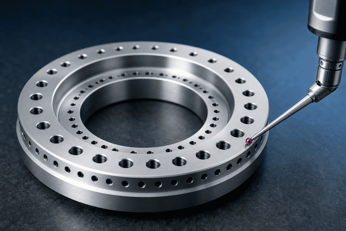
Where a coordinate measuring machine or optical comparator is available, use it to verify hole patterns and concentricity. For simple incoming checks, go/no-go gauges and pin gauges can confirm hole sizes and positions. Record actual values rather than pass/fail only, so that trends can be reviewed over time. Documenting actual values also builds a baseline for future replacement of VAD torch gas distribution components.
Threaded connections deserve attention because repeated disassembly can damage threads that still pass a visual check. Verify thread class, check for cross-threading, and confirm that thread depth meets the drawing. Where a torque specification exists, note it on the inspection record so that assembly follows the same target each time. Consistency in assembly torque is one of the less obvious factors that keeps sealing performance stable across maintenance cycles.
Visual and Surface Inspection
Look for scratches, burrs, dents, corrosion, and embedded particles on sealing faces and gas passages. Burrs near gas holes can disturb flow. Debris left in internal channels can migrate during operation. If the component has been cleaned or reworked, verify that cleaning residues or abrasive media are not present. Visual inspection of incoming VAD torch gas distribution components should always be done under adequate lighting and, where necessary, with magnification.
Document the location of any surface anomalies on a sketch or photograph so that future inspections can compare the same area. A scratch that is cosmetically minor on an external surface can be a rejection criterion on a sealing face, so the inspection record should state which face was affected and how the finding relates to the drawing requirement.
Pressure and Leak Checks
Where the equipment documentation and site procedures allow, perform a leak check on sealed channels before installation. The method, pressure, and acceptable leak rate should come from the equipment manufacturer’s documentation or an approved internal procedure. Do not improvise pressure settings or use hazardous gases for inspection unless qualified personnel and proper equipment are available. For more details on manifold design and connection verification, see the guide to an OVD oxygen distribution manifold with custom machining and connection checks.
A leak check that is performed correctly also validates the sealing face condition and the assembly torque applied during the test. If a channel passes at one torque and fails at another, that result is useful information about sealing face flatness or gasket behavior rather than a simple pass or fail. Record the conditions under which the test was run so the result can be interpreted later.
Documentation Review
Confirm that the supplied component matches the approved drawing revision, material certificate, and any required inspection report. If the part is a replacement for an existing component, compare the new drawing against the removed part to confirm that no undocumented changes were made. Complete documentation records make it possible to trace performance issues back to specific batches of VAD torch gas distribution components.
For related inspection and maintenance logic, the case study on upgrading OVD torch consumables to titanium alloy for a global Tier-1 fiber manufacturer discusses wear patterns and lifespan considerations that can inform inspection intervals. For issues that appear after installation, such as soot clogging on burner faceplates, inspection findings should be compared with process data before concluding that the gas distribution component is the cause.
Common Drawing and Inspection Problems
Several recurring problems can make VAD torch gas distribution components difficult to source or verify.
Incomplete Datum Definition
If the drawing does not clearly identify functional datums, a machinist may choose a different reference than the one used by the original equipment. This can shift hole positions or concentricity relative to the mounting interface. Specify datums that reflect how the part locates in the torch.
Missing Angular Relationships
On multi-ring components, the angular clocking between rings can affect gas mixing. If the drawing shows only individual hole positions without defining the relationship between rings, the assembled result may not match the intended flow pattern. Missing angular relationships are one of the most common reasons VAD torch gas distribution components perform differently from the original equipment even when nominal dimensions look correct.
Surface Finish Ambiguity
Specifying a single surface finish for all faces is rarely appropriate. Sealing faces, gas passage walls, and external surfaces have different requirements. Define finish by function and, where possible, by the seal type or flow requirement. When several VAD torch gas distribution components are machined from the same drawing, ambiguous finish calls can create inconsistent results between suppliers or production runs.
Material Substitution Without Review
If a supplier proposes a substitute material, review it against temperature exposure, chemical compatibility, and mechanical properties. A material that works for one torch component may not be suitable for another. The key questions before custom machining VAD cladding burner components guide explains how process differences can affect component requirements.
Sourcing Questions for VAD Torch Gas Distribution Components
When requesting a quotation or starting a custom manufacturing project, provide as much of the following information as possible:
- Approved drawing with revision number and datums
- Material specification, condition, and any heat treatment
- Surface finish and flatness requirements for sealing faces
- Gas hole sizes, positions, and angular relationships
- Mounting interface dimensions and alignment features
- Quantity and whether the part is a one-time replacement or recurring need
- Any inspection report or material certificate required
- Operating conditions that affect material or coating selection
If a drawing is not available, a dimensional inspection of the removed component can support reverse engineering. For standard replacement components, the optical fiber equipment parts range may include related torch and deposition components, but compatibility must always be verified against drawings, dimensions, gas connections, materials, and application requirements. This is where custom VAD core deposition burner parts and OEM/ODM machining services can help convert measured data into a production drawing.
When several identical parts are needed across multiple torches, state the expected annual quantity and whether interchangeability between torches is required. A supplier who knows the parts will be rotated across lines can propose markings and inspection records that make rotation easier to manage. Where possible, include a representative sample or a drawing of the mating interface so the machinist can verify fit without making assumptions about the surrounding hardware.
FAQ
Can VAD gas rings be used in an OVD torch?
Not necessarily. VAD and OVD use different deposition geometries and torch arrangements. Even if the mounting interface appears similar, gas hole patterns, concentricity requirements, and thermal conditions may differ. Verify against the equipment documentation and the actual drawing before substitution.
What is the most important inspection check for a new gas distribution component?
There is no single answer for every part. In general, verify the features that control gas flow and sealing: hole geometry, concentricity, and sealing face condition. The priority depends on the component’s function in the torch.
How do I know if a gas distribution component is causing a deposition problem?
Deposition problems can have multiple causes, including gas flow settings, precursor delivery, thermal conditions, and mechanical alignment. Inspecting the gas distribution component is one part of a broader troubleshooting process. Compare inspection findings with process data and equipment documentation before concluding that the component is the root cause.
How often should VAD torch gas distribution components be inspected?
Inspection intervals depend on operating hours, cleaning cycles, and observed wear. Many teams inspect at each scheduled disassembly and record dimensional values so that gradual changes become visible before they cause deposition problems. Trending the data is often more useful than a single pass or fail result.
Can OVDParts manufacture a replacement from a sample or drawing?
OVDParts offers custom precision machining for optical fiber equipment components. Providing a drawing with defined datums, materials, and inspection requirements supports an accurate quotation. If only a sample is available, dimensional inspection can be used as a starting point for reverse engineering. Contact the team to discuss the specific component and requirements.
To move forward, prepare the drawing, dimensions, material specification, and operating conditions for the VAD torch gas distribution component you need. Contact our team to discuss the requirements or request a quotation. Clear, complete inputs are what allow replacement VAD torch gas distribution components to match the performance of the original assembly, and careful drawing and inspection practices are what keep that performance stable over the life of the torch.
Expand Your Knowledge with Additional Resources
For further reading on the technical standards that underpin precision gas distribution component manufacturing, consult the ISO 9001:2015 quality management standard or the ASME codes and standards for machining and materials. On the metrology side, the NIST physical measurement laboratory reference material on dimensional metrology provides background on how dimensional measurements are traced to national standards, which supports the inspection approach described here.
