
Knowledge
Managing Internal Aerodynamics: Pressure Balancing and Gas Flow Dynamics in Multi-Channel OVD/VAD Torches
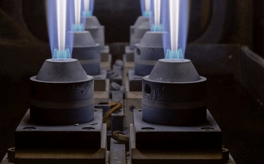
Oct
In optical fiber preform manufacturing, the precision of your mass flow controllers (MFCs) means very little if the physical channels inside your deposition burner fail to distribute that gas uniformly. Process engineers often spend weeks calibrating gas ratios—adjusting standard liters per minute (SLM) of silicon tetrachloride (SiCl₄) against shielding lines of oxygen (O₂) and hydrogen (H₂). Yet, erratic flame patterns, high chemical wastage, and internal deposition often persist.
The root cause is rarely the electronic gas mixing system. Instead, it lies within the internal fluid dynamics and pressure balancing of the burner body itself.
For an Outside Vapor Deposition (OVD) or Vapor Axial Deposition (VAD) torch to deliver a stable, high-yield soot boule, the internal machining must ensure that gases moving at different velocities equalize completely before they reach the nozzle face. Let’s break down the hidden aerodynamics inside a multi-channel burner and look at how internal machining tolerances dictate gas behavior.
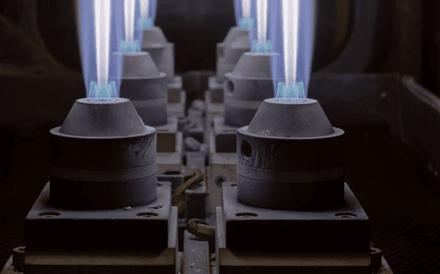
(Our 4-port OVD burner nozzle assembly is engineered with precisely these aerodynamics in mind.)
1. The Challenge of Multi-Layer Gas Distribution Plenums
An OVD or VAD burner is essentially a complex chemical manifold wrapped in a compact metal housing. It typically features concentric layers routing three distinct gas categories:
-
The Core Chemical Stream: Vaporized SiCl4 and GeCl4 carried by an inert gas (like Argon or Nitrogen).
-
The Shielding Gas Layer: An intermediate buffer gas ring designed to prevent the raw chemical stream from touching the burner face prematurely.
-
The Combustion Mixture: Concentric rings of H2 and O2 that ignite to create the high-temperature hydrolysis zone.
[Gas Inlet Ports] ──> [Internal Expansion Plenums] ──> [Distribution Baffles] ──> [Concentric Nozzle Rings]
   (High Pressure)          (Velocity Reduction)         (Pressure Equalization)         (Laminar Exit Velocity)
When these gases enter the base of the burner through individual threaded fittings, they arrive as high-velocity, turbulent streams. The interior of the burner must act as an expansion and equalization plenum.
If the internal baffles or milled expansion slots contain asymmetric variations as small as 10 microns, the gas will take the path of least resistance. This creates a pressure imbalance across the circumference of the nozzle, causing the exit velocity to be higher on one side than the other, resulting in a skewed flame that misses the optimal deposition target.
(“To understand how this precision requirement scales down to the nozzle face, read our article on Burner Nozzle Precision & Preform Yield)
2. Preventing Back-Diffusion: The Costliest Failure Mode
One of the most destructive phenomena on a deposition line is back-diffusion. This occurs when the static pressure of the outer combustion or shielding gas rings exceeds the pressure of the core chemical stream, or vice versa, causing gases to cross-contaminate inside the burner body.
If ambient moisture or oxygen backs up into the SiCl4 distribution plate during a low-flow phase or an abrupt shutdown sequence:
-
The hydrolysis reaction occurs internally.
-
Hard, glassy silica scale forms inside the hidden, microscopic channels of the gas distribution blocks.
-
Once internal scaling begins, the burner is permanently compromised, altering flow coefficients and rendering your MFC calibrations highly inaccurate.
To prevent back-diffusion, the internal mating faces of the distribution plates must be machined to a mirror-like flatness. This allows for an absolute mechanical, metal-to-metal face seal that eliminates the reliance on rubber O-rings, which brittle and fail when exposed to hot, corrosive chlorine vapors.
3. Maintaining the Laminar Boundary Layer: Eliminating Internal Cross-Talk
For the shielding gas to effectively isolate the raw SiCl4 vapor from the hot combustion nozzle, it must exit the burner face in a state of perfect laminar flow (a low Reynolds number).
If the internal multi-channels that feed the shielding ring suffer from machining irregularities—such as chatter marks from an uncalibrated milling cutter or mismatched steps from a multi-setup machining process—the gas stream becomes turbulent.
Turbulent shielding gas mixes with the core chemicals right at the exit boundary. Instead of a clean, projecting plume of soot particles drifting onto the target mandrel, you get premature crusting on the burner head. This crusting distorts the flame profile and forces operators to stop a multi-hour preform run prematurely to clean or swap the burner assembly.
Single-Setup Precision: Engineering the Ultimate Industrial Flow Path
Overcoming these internal aerodynamic hurdles requires moving away from traditional, multi-stage machining methods. When an internal gas block is moved from a lathe to a separate milling machine, clamping stack-up errors are introduced, misaligning the internal flow paths.
At SKY CNC., we eliminate these internal flow discrepancies at the source. Leveraging 22 years of high-tolerance CNC turn-mill expertise, our main manufacturing infrastructure, detailed at sky-cnc.com, is designed to execute multi-axis, complex internal machining within a single, unified machine setup. Through our dedicated division at ovdparts.com, we bring this extreme machining discipline directly to the global optical fiber industry.
Our internal expansion chambers, gas distribution plates, and concentric micro-hole arrays are engineered to achieve perfect internal pressure equalization. This attention to internal aerodynamic detail is why our factory-direct replacement components are trusted daily on the high-intensity production lines of global optical fiber market leaders, including YOFC, Hengtong Optic-Electric, ZTT, Futong Group, Yongding Stock, Tongding Interconnection, and SDG Information.
By ensuring absolute internal alignment and flawless metal-to-metal face sealing, we provide OVD and VAD replacement burners that maintain highly stable flow coefficients, maximize your chemical-to-soot deposition efficiency, and actively protect your cleanroom from expensive mid-cycle failures.
Optimize Your Fluid Dynamics with a Trusted Supply Line
Your deposition efficiency is entirely bound to the internal geometry of your burners. Whether you are troubleshooting flame instabilities on our 4 standard stock models, or need to prototype a non-standard, custom multi-channel torch array with proprietary internal baffling, our engineering cell is equipped to manufacture to your exact parameters under a strict, legally binding Non-Disclosure Agreement (NDA).
Take control of your deposition aerodynamics. Upload your STEP/CAD drawings or contact our technical engineers for a fluid-path review today at ovdparts.com.
