
Knowledge
Preform Lathe Chuck Components: Custom Machining and Workholding Checks
Oct
Preform Lathe Chuck Components sit at the point where precision workholding meets high-temperature deposition. For engineers running OVD, VAD, or MCVD processes, the chuck is not just a mounting device — it establishes the rotational axis that the burner, torch, or traverse system references throughout the run. When chuck jaws wear, seating surfaces degrade, or a replacement jaw set is machined without full dimensional data, the resulting runout shows up as soot deposition asymmetry, taper variation, or inconsistent refractive index profiles long before anyone suspects the workholding.
This article covers what to inspect on preform lathe chuck components, how to evaluate custom preform chuck parts before ordering, and what information a machine shop needs to produce replacement workholding that matches the original design intent.
What Preform Lathe Chuck Components Actually Do
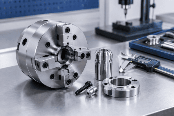
A preform lathe holds a glass bait rod, target rod, or starting tube while burners deposit soot or while the preform is consolidated and stretched. The chuck — whether a three-jaw scroll, a collet-style closer, or a custom split-clamp design — must do three things simultaneously:
- Transmit torque without slipping at the operating rotational speed
- Maintain radial runout within the tolerance required by the deposition process
- Repeat the clamping position closely enough that preform-to-preform variation stays controlled
These functions are interdependent. A chuck that grips securely but introduces axial tilt will produce a curved preform axis. A chuck with excellent runout but insufficient clamping force can allow micro-slippage during acceleration, which shows up as surface marks or localized diameter variation.
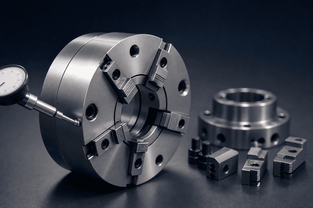
The components involved typically include jaw inserts or contact pads, jaw carriers, scroll plates or clamping rings, backplates, adapter plates, and sometimes custom spacer or alignment features that locate the chuck on the lathe spindle. Each of these can wear, distort, or be damaged independently. The overall condition of these preform lathe chuck components determines how repeatable the deposition process can be.
Inspection Points for Precision Workholding Components
Before ordering replacements, it helps to determine which component is actually causing the problem. Replacing an entire chuck assembly when only the contact pads are worn is expensive and unnecessary; conversely, machining new jaws for a distorted scroll plate will not restore concentricity.
Jaw contact surfaces and inserts
Jaw inserts that contact the glass or the carrier rod are the most common wear item. Look for:
- Contact pattern: A uniform, full-width contact mark along the jaw face suggests even loading. Concentrated marks at one end indicate angular misalignment or a bent jaw.
- Embedded particles: Glass chips, soot, or abrasive debris pressed into soft jaw material can scratch the rod and reduce grip consistency.
- Deformation: Over-tightening or thermal exposure can bell or mushroom the jaw face, reducing effective contact area.
- Material condition: Inserts may be machined from aluminum, bronze, polymer composites, or other materials depending on the application. Material choice should be based on contact pressure, temperature at the chuck, contamination risk, and whether the insert must yield slightly to avoid damaging the glass. Aluminum is sometimes used for lighter contact or where thermal conductivity helps, but it should not be assumed suitable for every chuck position — see aluminum OVD parts for context on where aluminum components are typically applied.
Scroll plates, clamping rings, and actuation surfaces
Scroll chucks rely on a spiral plate that moves all jaws simultaneously. Wear in the scroll teeth produces uneven jaw advance, which means the rod is not centered even when the jaws appear to close evenly. Check for:
- Visible wear or galling on the scroll spiral
- Backlash when reversing jaw direction
- Jaw-to-jaw position variation when closing on a known round gauge
On collet-style or split-clamp chucks, inspect the closing taper and the flexure region for cracks, permanent set, or uneven contact.
Backplates and spindle interfaces
The backplate or adapter that mounts the chuck to the lathe spindle establishes the reference plane. Dirt, burrs, or fretting corrosion on this interface can tilt the entire chuck. Even a small angular error at the backplate is amplified at the far end of a long preform.
Check the mounting face for flatness, the register diameter for fit, and the bolt holes for elongation or thread damage. On custom chucks, verify that the register fits the spindle nose without force and without perceptible play.
Runout measurement
Radial runout should be measured with the chuck mounted and actuated as it would be in production. Use a dial indicator on a known cylindrical surface — a test bar or a ground gauge — at both the chuck face and at a distance representing the working position of the preform. Record the runout at multiple rotational positions. If runout varies with jaw position rather than rotation angle, the problem is in the jaws or scroll; if it repeats once per revolution, the issue may be in the spindle, backplate, or chuck body.
Workholding interface checks beyond the chuck
The chuck is only one element of the workholding interface. The tailstock, steady rest, and any intermediate support also influence the preform axis. If the chuck is centered but the tailstock is offset, the preform will bow. Inspect tailstock center runout, steady-rest pad condition, and the alignment between headstock and tailstock over the full travel. For lathes that have been moved or re-leveled, this alignment should be re-verified before blaming the chuck.
Spindle taper and drawbar condition also matter for collet-style chucks. A worn taper or a stretched drawbar reduces clamping force and can allow the collet to seat off-axis. Measure drawbar extension and check the taper for scoring or fretting.
For engineers working with deposition torch alignment, the workholding interface is part of a larger alignment chain. The article on optical fiber preform equipment and deposition torch parts covers related technical and sourcing questions that often come up alongside chuck work.
When to Machine Custom Preform Chuck Parts
Custom preform chuck parts become necessary when original components are no longer available, when the chuck has been modified for a specific lathe or preform size, or when the existing design does not hold up in service. Custom machining is also common when a production team wants to change contact pad geometry for a different rod diameter or to reduce marking on the glass.
Typical custom parts include:
- Replacement jaw inserts with modified contact geometry or material
- Adapter plates for mounting a chuck on a different spindle interface
- Split-clamp halves machined to a specific preform diameter
- Spacer rings and alignment sleeves that set axial position
- Non-standard backplates where the original is damaged or unavailable
For any of these, OEM/ODM machining services can produce parts from drawings, samples, or measured dimensions. The critical input is not the part name but the functional requirements: what the part must locate, what load it carries, what temperature it sees, and what material is appropriate.
Information to provide for a custom chuck component quote
A machine shop cannot produce a reliable workholding component from a description alone. Useful inputs include:
- Drawings or sketches with critical dimensions, tolerances, and datums. If no drawing exists, provide a physical sample or detailed measurements.
- Material specification or the material of the original part. If the original material is unknown, describe the operating environment — temperature, humidity, contact with glass, cleaning agents — so the shop can recommend a suitable alloy or polymer.
- Interface dimensions: spindle register diameter, bolt circle, jaw slot dimensions, and any keyway or locating feature.
- Operating conditions: rotational speed range, clamping force, rod diameter and weight, and whether the chuck sees radiant heat from the burner or torch.
- Quantity and lead time expectations, recognizing that prototype quantities and production quantities may follow different processes.
- Inspection requirements: which dimensions are critical, and whether a dimensional report is needed.
Photographs of the installed chuck, the worn area, and the spindle interface are often as valuable as a drawing because they show how the part actually fits and wears.
Reverse engineering from an existing component
When drawings are unavailable, reverse engineering from a sample is a practical route. Accuracy depends on the condition of the sample and the measurement methods used. A worn jaw insert, for example, may no longer represent the original contact geometry, so the shop must distinguish between intentional features and wear. Hardness testing, material analysis, and careful measurement of unworn reference surfaces help separate design intent from service damage.
For chucks used on SG Controls or similar MCVD lathes, the mounting interface and jaw geometry may be specific to that platform. The guide to SG Controls MCVD lathe spare parts describes typical custom machined holders and carriage components, which provides useful context for how workholding interfaces are documented and reproduced.
If the original chuck design used interchangeable inserts, it may be possible to standardize on a new insert geometry that improves grip or reduces glass marking without modifying the carrier. This kind of incremental change is often more cost-effective than a complete chuck redesign.
Workholding Checks Before and After Replacement
Installing a new or re-machined chuck component without verification can introduce a new error. A simple sequence helps confirm that the workholding is not the source of process variation:
- Clean all interfaces before assembly. Soot, glass dust, and dried lubricant are common causes of tilt and runout.
- Check register fit by hand. The chuck should seat fully without rocking.
- Torque fasteners evenly in a crossing pattern to avoid distorting the backplate.
- Measure runout at the chuck and at working distance after assembly, using a gauge that represents the preform diameter.
- Clamp a test rod and check for axial tilt by measuring at two points along the rod.
- Run a short deposition or rotation test if the process allows, and compare the result against a known-good baseline.
If runout changes after clamping, the issue may be in the jaw contact or scroll rather than the spindle. If runout is constant but high, the backplate or spindle interface is the more likely source.
Workholding problems sometimes present as deposition problems. If soot deposition becomes asymmetric or the preform develops a taper, the chuck may be contributing. Related diagnostic logic is discussed in the article on refractive index profile drift and burner concentricity, and in the guide to preform end-taper thermal stress, but the chuck should be checked before adjusting burner parameters.
Document the baseline measurements. A simple log of runout at the chuck face and at working distance, recorded after each rebuild, makes it easier to distinguish sudden changes from gradual wear. It also gives the machining team a reference when producing replacement preform lathe chuck components.
Material and Design Considerations for Chuck Components
Material selection for precision workholding components depends on the specific function:
- Contact pads and jaw inserts: Must balance grip, wear resistance, and protection of the glass surface. Hard materials resist wear but may mark or chip the rod; softer materials protect the glass but wear faster and may embed debris.
- Structural components (backplates, jaw carriers): Need dimensional stability and adequate stiffness. Thermal expansion mismatch between the chuck and the spindle can change runout as the lathe warms up.
- Components exposed to heat: If the chuck is close to the deposition zone, radiant heating may cause expansion or material degradation. The appropriate material depends on the actual temperature at that location, which should be measured rather than assumed.
Because these requirements vary by lathe, preform size, and process, it is worth reviewing the range of optical fiber equipment parts available as standard items before committing to a fully custom design. In some cases a standard component can be adapted; in others, custom machining is the more reliable route.
Design choices also affect maintainability. Inserts that can be replaced without removing the chuck from the spindle reduce downtime, and clearly defined datums make it easier to verify alignment after service. For lathes that run multiple preform sizes, interchangeable jaw sets or adjustable stops can reduce changeover time while preserving the reference surfaces that keep runout predictable.
Tolerances should match function. Over-tight tolerances on non-critical features increase cost without improving performance, while loose tolerances on locating surfaces directly affect runout. The drawing should identify which dimensions are functional and which are reference only.
How Preform Lathe Chuck Components Fit Into the Wider Deposition Process
The chuck does not operate in isolation. It interacts with the burner traverse, the gas delivery system, and the exhaust flow. Runout in the chuck changes the distance between the burner face and the glass surface, which in turn affects deposition efficiency and soot density. Even a small eccentricity can produce a periodic variation that looks like a burner pulsing problem.
For this reason, maintenance planning should treat the workholding and the deposition torch as a single alignment chain. When a burner is replaced or repositioned, it is worth confirming that the chuck is still centered and that the preform axis has not shifted. Conversely, when a chuck is rebuilt, the burner alignment should be re-checked before the next production run.
Burner components themselves are subject to wear and can introduce their own variation. Sourcing guides such as the Nextrom VAD burner replacement parts guide or the overview of OVD burner parts explain how those consumables are specified and replaced. Keeping both the workholding and the burner in specification reduces the chance of misattributing a deposition defect to the wrong subsystem.
For processes that require precise refractive index profiles, the combination of chuck runout, burner concentricity, and traverse stability determines the final result. Measuring each contribution separately is the only reliable way to isolate a problem when the profile drifts.
FAQ
How often should preform lathe chuck components be inspected?
Inspection frequency depends on operating hours, rotational speed, and contamination levels. A practical approach is to check jaw contact patterns and runout at each scheduled maintenance interval, and to inspect immediately after any incident that could have overloaded the chuck — a jam, a crash, or a preform break during rotation. Trending runout measurements over time is more useful than a single check because it reveals gradual wear. Many facilities find that inspecting these preform lathe chuck components at every major maintenance window is sufficient, with additional checks after any abnormal event.
Can worn chuck jaws be repaired instead of replaced?
In some cases, jaw inserts can be re-machined or replaced while the jaw carrier is reused. This depends on whether the carrier itself is distorted and whether re-machining would remove too much material or change the clamping geometry. For scroll plates with worn teeth, repair is rarely practical, and replacement is usually more reliable. A machine shop can assess the worn part and advise based on measured condition. When repair is chosen, the resulting preform lathe chuck components should be re-measured to confirm that clamping geometry still meets the original specification.
What is the most common cause of runout in a preform lathe chuck?
Contamination or damage at the spindle-to-backplate interface is one of the most frequent causes, followed by uneven jaw wear. Because the interface error is amplified over the length of the preform, a small amount of debris or a burr can produce significant runout at the working position. Cleaning and inspecting this interface is a logical first step before suspecting the chuck body or jaws. If the interface is clean and the runout persists, then the jaws, scroll, or spindle bearings become the next candidates.
Can OVDParts reverse-engineer a chuck component from a sample?
Reverse engineering from a physical sample is possible when the sample is complete enough to measure critical features and when the material can be identified or a suitable substitute specified. The more dimensional and functional information provided, the more reliable the result. For components where the sample is worn or incomplete, drawings and interface measurements from the lathe are important supplements. In many cases, a combination of a worn sample and a few key measurements from the machine is enough to produce replacement preform lathe chuck components that restore original performance.
Next Step
If you are evaluating replacement preform lathe chuck components or planning a custom workholding project, gather the drawings, sample measurements, material details, and operating conditions described above. Sharing these inputs with the manufacturer allows a more accurate assessment of feasibility and cost. To discuss a specific component, contact our team with your dimensions, material requirements, and the operating conditions the part must withstand.
For broader context on preform equipment parts and how they are sourced, the ISO 10110 optical drawing standard provides useful guidance on specifying tolerances for optical components, which can inform how you document critical dimensions on your own drawings.
