
지식
Deposition Burner Reverse Engineering: Avoiding Dimensional Errors
10월
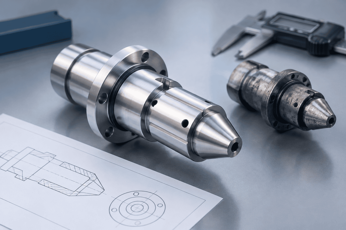
Deposition Burner Reverse Engineering is often treated as a measurement exercise: capture the geometry of an existing torch, reproduce it, and put the replacement into service. In practice, the dimensions that matter most are frequently the ones that are hardest to measure — the original design intent behind a part that has already been eroded, distorted, or rebuilt. Worn burner part measurement errors rarely announce themselves at the dimensional inspection stage.
They surface later as flame asymmetry, shifted deposition patterns, or preform quality drift that is difficult to trace back to a single suspect component. For engineers and maintenance teams working on OVD and VAD lines, deposition burner reverse engineering is less about copying a part and more about reconstructing a specification that was never fully documented. This article explains where dimensional errors originate in custom burner replacement projects, how to measure worn parts more defensibly, and what to document before releasing a drawing for production.
Why Deposition Burner Reverse Engineering Is Different From Copying a Part
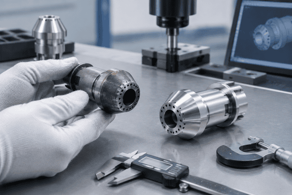
A deposition burner is a gas-distribution device, not a passive bracket. Its function depends on the relationship between multiple internal channels, the faceplate geometry, and the way the torch mounts relative to the deposition axis. As a result, “matching the sample” is an incomplete specification. Two burners can measure identically at the nozzle face and behave differently because of internal channel alignment, seat depth, or how the assembly preloads when hot.
That distinction matters most when the sample part is worn. If the reference component has been in service, the drawing you generate from it captures a degraded state, not the state the equipment was commissioned with. Any deposition burner reverse engineering effort therefore has two objectives that must be kept separate: reconstructing the as-built geometry, and identifying which deviations from that geometry are wear rather than design.
Where the burner is part of an OVD or VAD preform line, the geometry also interacts with the soot deposition process itself. Small shifts in nozzle exit position or faceplate flatness can change the shape of the soot stream before any downstream process variable changes. That coupling is why a dimensional error in a burner is rarely just a dimensional error; it becomes a process shift.
Where Dimensional Errors Enter the Process
1. Using a worn part as the sole reference
Erosion, thermal distortion, and soot buildup all change measurable geometry. A nozzle orifice that has gradually opened, a faceplate that has warped slightly, or a seating shoulder that has been compressed over many thermal cycles will all produce a “correct” measurement of an incorrect shape. When only one sample exists, the risk is highest, because there is no second data point to separate design from degradation.
Verification approach: compare the suspect part against any available unworn or low-hour counterpart, against original equipment drawings if the customer holds them, or against the dimensional relationships implied by mating components. Where several identical burners are in service, measuring across the set and identifying the common geometry is often more reliable than trusting any single unit. A deposition burner reverse engineering project that begins with a single worn part should treat every dimension as provisional until a second reference confirms it.
2. Measuring in the wrong reference frame
Deposition burner dimensions are meaningful relative to functional datums — typically the mounting interface, the gas inlet face, or the axis of the central channel — not relative to whatever surface is convenient to clamp. If a coordinate measuring machine setup references a corroded exterior surface, every downstream dimension inherits that error. In deposition burner reverse engineering, the choice of datum is arguably the single most consequential decision in the entire measurement plan.
Verification approach: define datums from features that are both functional and stable. Mounting bores and machined seats usually qualify; exterior surfaces exposed to flame or process atmosphere usually do not. Document the datum scheme on the drawing so the machine shop reproduces the same reference logic rather than re-deriving it.
3. Ignoring thermal and assembly state
A burner measured cold, disassembled, and at room temperature is not in the same geometric state as a burner at operating temperature with its joints loaded. Differences in thermal expansion between internal components can shift relative positions in ways that matter for gas distribution. This does not mean every dimension needs a hot-state correction, but it does mean the measurement report should state the condition under which dimensions were taken — an omission that invalidates many a deposition burner reverse engineering report that otherwise looks complete. Reports that omit the measurement condition force the reader to assume, and assumptions compound.
4. Averaging away real asymmetry
Some deposition burners are intentionally asymmetric, and some become asymmetric through wear. Treating a set of hole positions as “nominally evenly spaced” when the data shows a consistent offset will erase a real design feature — or preserve a real defect. Statistical averaging is useful for identifying outliers, but it should not override the actual measured pattern without a reason.
5. Losing information at the drawing stage
Even accurate measurements can be undermined by a drawing that omits critical relationships. Angular orientation of a nozzle array, the depth and concentricity of a gas seat, surface finish on a sealing face, and the position of a feature relative to a datum rather than to another feature all influence function. If the drawing shows hole diameters but not their angular clocking, the replacement may be dimensionally compliant and functionally wrong.
Related considerations for multi-channel geometry are covered in this discussion of OVD, VAD, and MCVD burner parts and which components need separate specifications.
A Practical Measurement Workflow for Worn Burner Parts
The following sequence is intended to reduce the chance that wear is mistaken for design. It is a documentation discipline, not a substitute for the equipment manufacturer’s procedures or for qualified metrology support. Teams new to deposition burner reverse engineering often find that the workflow itself surfaces ambiguities that were invisible during informal inspection.
- Record service history first. Hours in service, process conditions, cleaning methods, and any prior repairs all inform how much degradation is plausible. A part with an unknown history should be treated as a higher-risk reference.
- Photograph before cleaning. Deposits, discoloration, and erosion patterns are evidence. Clean the part only after the as-received condition is documented.
- Establish functional datums. Identify the mounting and sealing interfaces and confirm they are not themselves worn. If a datum feature is damaged, note it explicitly rather than assuming it is nominal.
- Measure the full feature set, not just the obvious ones. Include internal channel diameters and straightness, seat depths, faceplate flatness, angular positions, and the concentricity of coaxial features.
- Measure mating components too. The counterpart part often reveals what the worn part once was, particularly for seat depths and interference relationships.
- Flag every dimension with a confidence level. Distinguish measured-and-verified, measured-but-suspect, and inferred-from-mating-parts. This flagging is what allows a machine shop to ask the right questions instead of guessing.
- State material and condition requirements separately. Geometry and material are independent specifications; neither should be inferred from the other.
- Review the datum scheme against the process role. Confirm that the features being used as references are the same ones that govern how the burner sits in the deposition lathe and how gas enters the torch.
On OVD and VAD torches specifically, it is worth measuring the auxiliary or tail burner interface at the same time as the main deposition burner. Wear at the tail burner mount can shift the apparent position of the main torch, producing a measurement that looks like main-burner error but is actually a fixture or interface problem. A deposition burner reverse engineering review that ignores neighboring components can send the project in the wrong direction. Engineering teams documenting their own dimensional measurement schemes may also find general guidance in published university metrology resources such as NIST’s dimensional metrology program overview.
Material and Functional Considerations in Custom Burner Replacement
Dimensional accuracy alone does not produce a working burner. The material selected for each component must suit its actual function — the temperature it sees, the gases it contacts, its thermal expansion relative to adjacent parts, and its machinability at the required feature sizes. A material that performs well for a structural bracket may be entirely unsuitable for a faceplate or a nozzle insert, and vice versa.
This is one reason deposition burner reverse engineering projects benefit from a clear functional description alongside the drawing. When a replacement is intended for an OVD torch, for example, the component’s role within the OVD 버너 부품 assembly — gas distribution, sealing, structural support, or mounting — should be stated so that material and tolerance decisions follow function rather than habit.
Guidance on matching materials to burner duty is available in this guide to custom OVD and VAD burner sourcing and reverse engineering.
It is equally important not to assume that components are interchangeable across processes. OVD, VAD, and MCVD torches differ in nozzle arrangement, thermal environment, and gas delivery strategy; a part that functions correctly in one process is not automatically suitable in another. For broader industry context on how these processes relate to optical fiber manufacturing, see the Corning overview of optical fiber technology.
Surface treatment decisions deserve the same scrutiny. A coating that improves wear resistance in one environment may introduce contamination in another, and a polished sealing face may be functionally necessary but geometrically delicate. The deposition burner reverse engineering specification should therefore include surface finish and treatment as distinct requirements, not as implicit consequences of material choice.
Consequences of Dimensional Errors That Reach Production
Errors that survive into a finished replacement part tend to appear as process symptoms rather than as obvious defects:
- Flame asymmetry or tilt when channel geometry or angular orientation deviates from the original.
- Deposition rate changes when nozzle exit geometry alters the soot stream.
- Profile drift when concentricity between coaxial features is not maintained.
- Sealing problems when seat depth or face flatness is outside the functional range.
- Shortened service life when material or surface condition does not match the thermal and chemical environment.
Because several of these symptoms have multiple possible causes, a dimensional deviation should be treated as a candidate explanation rather than a confirmed diagnosis. Verifying it means checking the replacement against the documented datums, confirming that mating parts are also within specification, and reviewing whether the symptom appeared only after the change. Causes such as faceplate contamination or flame tilt have their own diagnostic paths, including soot clogging on OVD burner faceplates and the causes of OVD burner flame tilt.
In practice, the fastest way to narrow a suspect list is to compare the timing of the symptom to the timing of the replacement. A defect that appears immediately after a new part is installed points strongly to the replacement itself. A defect that develops gradually over dozens of deposition runs is more likely to be wear, contamination, or a process drift that happens to coincide with the new component. Records from a deposition burner reverse engineering file that include installation dates and run counts make this comparison possible.
Preparing a Sourcing Request That Avoids Ambiguity
Much of the dimensional risk in custom burner replacement is transferred, not eliminated, when a project moves from measurement to manufacturing. The supplier can only control what the request specifies. A package that supports a reliable quotation typically includes:
- Original drawings, if available, clearly marked as the primary reference.
- Measured data from the worn sample, with confidence flags and datum definitions.
- Mating component dimensions and their condition.
- Material requirements stated by function and environment, not by assumption.
- Required tolerances on functional features, with a note on which dimensions are non-critical.
- Operating conditions that affect material and geometry selection, described at the level the customer is able to share.
- Any known prior replacement history, including parts that were previously made by a third party.
Where original drawings do not exist and only a worn part is available, a supplier experienced in custom machining can help reconstruct the design intent, but the reconstruction is only as good as the measurement discipline behind it. Discussing the measurement basis before production begins is usually faster than resolving a discrepancy after delivery.
It also helps to state what is not known. A request that clearly identifies unknowns gives the supplier an opportunity to propose a measurement approach, suggest a destructive or non-destructive inspection, or flag a feature that cannot be reproduced from the available data. Pretending completeness is more dangerous than admitting gaps in deposition burner reverse engineering projects, because the gaps tend to surface during commissioning rather than during quotation.
자주 묻는 질문
Can a replacement burner be made from a single worn sample?
It can, but the result carries more risk. The supplier must distinguish design geometry from wear, and with only one reference there is no way to cross-check. Providing mating parts, service history, or any partial documentation improves confidence significantly.
How should tolerances be assigned when the original drawing is missing?
Assign tolerances by function. Features that control gas distribution, sealing, or concentricity need tight control; structural and mounting features often do not. Over-tolerancing everything raises cost without improving performance, while under-tolerancing a critical seat can cause functional failure.
Does material selection need to be resolved before measurement?
They can proceed in parallel, but material must be decided before manufacturing, because machinability, thermal expansion, and achievable surface finish all depend on it. Material choice should follow the component’s temperature exposure, gas environment, and mechanical role.
What is the most common cause of dimensional error in these projects?
Referencing measurements to the wrong datum, or treating worn geometry as nominal. Both are documentation problems more than metrology problems, and both are avoidable with a clear datum scheme and explicit confidence flags on each dimension.
How does deposition burner reverse engineering differ for OVD, VAD, and MCVD torches?
The measurement discipline is similar, but the features that matter differ. OVD and VAD torches place heavy emphasis on faceplate and multi-channel geometry because of the soot stream. MCVD torches often have different nozzle arrangements and thermal profiles. A deposition burner reverse engineering plan should state the process and the torch role before the feature set is defined.
Should the worn part be cleaned before it is measured?
Photograph and document the as-received condition first, then clean. Some deposits are themselves evidence of flow behavior and can indicate which channels were starved or overloaded. Cleaning before documentation destroys that information permanently.
다음 단계
If you are planning a deposition burner reverse engineering project, gather your available drawings, measured data, mating component dimensions, material requirements, and operating conditions into a single package before requesting quotes. Sharing those details with our engineering and quotation team allows the dimensional basis of the replacement to be reviewed at the start of the project rather than discovered during commissioning. A disciplined deposition burner reverse engineering file — one that separates design intent from wear, states its datums, and flags its uncertainties — is the most reliable way to avoid the dimensional errors that only appear once the torch is back on the line.
