
지식
OVD VAD MCVD Burner Parts: Which Components Need Separate Specifications
10월
Procurement teams often treat “burner parts” as a single category when sourcing for preform production. In practice, OVD VAD MCVD burner parts serve fundamentally different functions in each process, and a specification that works for one deposition method can cause serious problems in another. A nozzle diameter, a faceplate material, or a mounting interface that fits an OVD lathe may be completely unsuitable for an MCVD glass-working torch, even if both components are described as “burner heads.” Understanding which components genuinely need separate specifications — and which can share common standards — helps engineers and buyers avoid costly mismatches and speeds up the quotation process.
Why the Three Processes Cannot Share One Specification
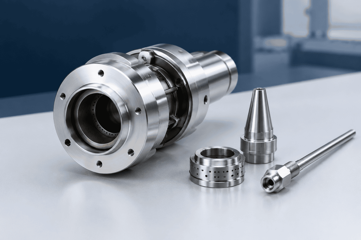
OVD (Outside Vapor Deposition) and VAD (Vapor Axial Deposition) both build a porous silica soot preform, but they do so in different geometries. OVD deposits soot radially onto a rotating target rod or bait rod, with the burner array typically positioned at a controlled distance from the growing surface. VAD deposits soot axially onto the end of a seed rod, so the burner faces the growth tip and the deposition geometry changes as the preform lengthens.
MCVD (Modified Chemical Vapor Deposition) is chemically and physically different again: precursor gases flow inside a rotating silica tube, and an external torch traverses the tube to drive the high-temperature reaction and subsequent sintering. MCVD is a deposition and consolidation process inside a substrate tube, not a soot-accumulation process on an outside surface. Because of these differences, the functional demands on OVD VAD MCVD burner parts diverge in at least four areas: thermal environment, gas chemistry, mechanical geometry, and positioning control.
Thermal and Chemical Environment Differences
The thermal and chemical conditions inside a torch or at a faceplate are not identical across the three processes, and those differences drive specification choices. OVD and VAD torches operate in an open deposition chamber where soot particles and process gases interact with the faceplate, while an MCVD torch heats a confined silica tube through its wall. Peak surface temperatures, heating and cooling rates, and the presence of reactive species all vary accordingly.
These factors influence the specification of key OVD VAD MCVD burner parts: which alloy or ceramic is appropriate, what surface treatment is needed, and how often inspection should occur. Documenting the thermal and chemical environment for each process — even qualitatively, referenced to equipment documentation — gives a supplier the context needed to recommend a suitable material and geometry rather than a generic alternative.
Components That Typically Require Separate Specifications
The following component groups almost always need distinct specifications per process. The exact numbers must come from the equipment drawings and process documentation; the purpose of this section is to identify where specifications should differ, so the right questions get asked. For a structured method, see the guide on sourcing custom OVD & VAD burners.
Burner heads and nozzle assemblies
OVD burner heads usually contain multiple gas channels arranged to produce a broad, stable soot stream across the preform surface. Channel count, spacing, orifice diameter, and exit geometry are all determined by the deposition rate and the target preform diameter. VAD burner heads generally face the growth end and must produce a flame pattern suited to axial deposition, which changes the required standoff and the way multiple channels are arranged relative to the growth axis. MCVD torches often use fewer channels and a different flame shape, because the goal is localized heating of a tube rather than soot delivery to an open surface.
This is why a nozzle geometry validated for one process should not be transferred to another without a drawing-based review. It is also why a mixed sourcing list that groups all OVD VAD MCVD burner parts under “burner nozzles” tends to produce mismatched components. Separate specifications for titanium OVD torch parts and for MCVD or VAD torch heads are the safer default.
Faceplates and deposition-facing surfaces
The faceplate is the component closest to the high-temperature reaction zone and is directly exposed to soot, radiant heat, and reactive species. In OVD and VAD, soot can accumulate on the faceplate over time; in MCVD, the torch faceplate is exposed to a different thermal cycle as it traverses the tube. Separate specifications should address surface finish, faceplate thickness, orifice edge condition, and material selection for each process. A faceplate optimized for soot shedding in an OVD environment may not be appropriate for the thermal cycling pattern of an MCVD traverse. For a closer look at deposition-side contamination, see the discussion of auxiliary tail burner replacement and interface checks.
Multi-channel gas distribution bodies
Multi-channel torches rely on internal passages that keep fuel, oxygen, and carrier or precursor flows separated until they reach the exit. The internal geometry — channel cross-sections, internal surface finish, sealing interfaces, and feed port layout — determines how evenly the flows are distributed. Because OVD, VAD, and MCVD torches operate with different gas combinations, flow ranges, and thermal loads, the internal aerodynamics requirements differ. A passage design that balances flows in one torch may create uneven distribution in another. The principles behind this are covered in the guide to VAD torch gas distribution components.
Mounting, adjustment, and kinematic interfaces
How a torch is held, aligned, and moved is process-specific. OVD and VAD systems use a deposition lathe with defined burner-to-target geometry; MCVD systems use a carriage that traverses the tube. The mounting flange, adjustment range, and alignment features must match each machine’s kinematic requirements. This category is often underestimated during sourcing, but an otherwise correct torch body can be unusable if its mounting interface does not match the lathe or carriage. For carriage-specific details, see MCVD burner carriage parts.
Which OVD VAD MCVD Burner Parts Can Be Shared — With Verification
Not every part needs three separate specifications. Some upstream or utility components can sometimes be standardized across processes, provided the operating conditions are compatible:
- Gas feed connectors and fittings — often shareable if thread, sealing method, and material compatibility match the process gas list. Verify against the equipment’s connection standard rather than assuming interchangeability. The OVD 버너 헤드 교체 가이드 covers common connection questions.
- Cooling or purge interfaces — sometimes common, but the required flow path and thermal duty should be confirmed for each process.
- Structural brackets and guards — frequently shareable if mounting geometry and thermal exposure are the same.
Even for shared components, material selection should be driven by the specific function, temperature exposure, chemical environment, and engineering requirements — not by a generic category label. Two torches that look similar externally may operate at different thermal loads and with different reactive species present. Where cladding hardware is involved, the questions in VAD cladding burner components help clarify the split between custom and standard items.
How to Build a Process-Specific Specification Package
A practical way to prevent mismatches is to maintain a separate specification record for each process family. Each record should capture, at minimum:
- Process identity and equipment reference — OVD, VAD, or MCVD, plus the machine or drawing number.
- Component function — soot delivery, tube heating, gas distribution, mechanical positioning, or utility interface.
- Interface dimensions — mounting pattern, gas port positions, sealing surfaces, and overall envelope.
- Thermal and chemical exposure — a qualitative description of the environment, referenced to the equipment documentation rather than guessed values.
- Material requirements — stated as a function of the application, not as a single fixed alloy or grade.
- Inspection criteria — what will be checked on incoming parts, such as orifice dimensions, surface condition, channel alignment, and sealing faces.
Keeping these records separate makes it obvious which components can be grouped in a single purchase order and which must be quoted individually. It also makes reverse-engineering projects faster, because a supplier receives a complete functional description rather than a part number alone. When drawings are incomplete, VAD core deposition burner parts can support drawing-based production and dimension-led reconstruction of non-standard components.
Material choice is part of that record, not an afterthought. Two OVD VAD MCVD burner parts with the same nominal alloy can behave differently after machining, welding, or prolonged thermal cycling. Documenting the specified grade, condition, and any post-machining treatment keeps later replacement orders consistent with the original build and prevents a well-intentioned substitution from changing the thermal response of the torch face. For additional reference on high-temperature materials behavior, see the material measurement work published by NIST.
Inspection and Verification Considerations
Because burner components directly influence deposition uniformity, inspection should focus on the features that affect flow and geometry. A mismatch among OVD VAD MCVD burner parts is often first noticed not at installation but as a drift in deposition behavior, so incoming checks deserve real attention. Useful checks include:
- Orifice and channel dimensions — measured against the drawing, with attention to edge condition and any burrs or deformation.
- Concentricity and alignment — particularly for multi-channel bodies, where channel misalignment can shift the flame or soot pattern.
- Surface finish on deposition-facing surfaces — relevant to soot adhesion and cleanability, though the required finish depends on the process.
- Sealing face condition — flatness and freedom from scratches, since gas leaks at internal interfaces are difficult to diagnose after installation.
- Mounting interface fit — verified against the lathe or carriage before the part is placed into service.
If a deposition problem appears after a component change — for example, a drift in deposition rate or an asymmetrical soot pattern — the cause is not automatically the new part. It should be verified through a structured check: compare the installed dimensions against the drawing, inspect the gas connections, review the alignment, and confirm that the process conditions match the specification.
Distinguishing a possible cause from a confirmed diagnosis prevents unnecessary replacement of components that are functioning correctly. It also protects the process history: when OVD VAD MCVD burner parts are changed without a recorded baseline, the next investigation has no reference point for comparison.
Documentation That Travels With Each Part
Specifications only prevent mismatches when they stay attached to the components they describe. A practical package includes the drawing revision, material certificate or stated grade, dimensional inspection record, and a short note on the intended process. For OVD VAD MCVD burner parts, that note should name the process explicitly, because a part record labeled only “burner nozzle” loses the context a future buyer needs.
Suppliers can also support this by returning the drawing revision they manufactured to, along with any approved deviations. If a deviation is accepted on one order, it should be reflected in the specification record so the next order does not silently drift from the validated geometry. This discipline matters most for flow-carrying and deposition-facing OVD VAD MCVD burner parts, where small dimensional changes can shift deposition behavior.
Common Sourcing Mistakes to Avoid
Several recurring errors cause mismatches when new OVD VAD MCVD burner parts are introduced into an existing process. A short review of these mistakes helps buyers and engineers catch problems before a purchase order is issued.
- Grouping all three processes under one part number. A shared stock code hides the differences that separate specifications are meant to capture.
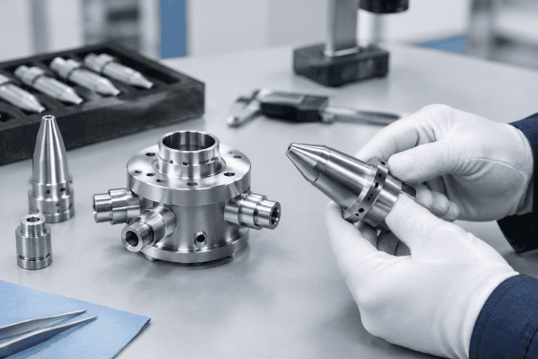
- Quoting from a photograph alone. Photographs cannot confirm internal channels, sealing faces, or gas port depths. Drawings or measured dimensions are needed.
- Assuming material equivalence. Similar-looking alloys may differ in thermal conductivity, oxidation resistance, or machinability.
- Skipping the mounting check. An interface that does not match the lathe or carriage makes an otherwise correct torch unusable.
- Treating inspection as optional. Without an incoming check on orifice and sealing features, a defect may only surface as a deposition problem.
Each of these mistakes is avoidable when the specification record is built around the process rather than the part category. The effort is modest, and it pays back in fewer rejected components and faster quotations.
Where Separate Specifications Save the Most Time
In practice, the components that benefit most from separate documentation are the ones closest to the reaction zone. Burner heads, faceplates, and multi-channel distribution bodies carry the greatest functional risk, because their geometry and material directly shape the flame, soot stream, or thermal profile. Utility fittings and structural brackets rarely justify three separate records, provided their dimensions and materials are verified.
For teams building a first specification set, starting with the flow-carrying and deposition-facing items is usually enough to prevent the majority of mismatches. The remaining items can be standardized later, once the operating conditions are confirmed.
Cost and Lead-Time Effects of Specification Splits
Splitting specifications across OVD VAD MCVD burner parts has a direct effect on cost and lead time, and it is worth understanding before a sourcing program begins. Components that need custom geometries, dedicated inspection criteria, or specific material certifications generally require a longer quotation cycle because the supplier must review drawings, confirm dimensions, and verify the proposed material against the intended process.
Standardized items — fittings, brackets, and utility interfaces — can often be quoted quickly and produced from inventory or routine stock. The practical effect is that a purchase order combining both categories will have a lead time determined by the slowest item. Breaking the order into groups by specification type helps buyers schedule the custom parts earlier and avoid holding up standard parts unnecessarily.
There is also a maintenance-planning angle. Custom burner components that are unique to a single process should be treated as critical spares with a defined review interval. When a spare is needed, the specification record should already exist so that no time is lost reconstructing dimensions or material requirements from the machine itself.
Practical Questions About Specification Splits
Can an OVD burner head be used on a VAD system?
Not without a full engineering review. OVD and VAD use different deposition geometries, so the required standoff, flame shape, and channel arrangement differ. Compatibility must be confirmed against the equipment drawings, dimensions, gas connections, and application requirements rather than assumed from a shared category name.
Are MCVD torch parts ever interchangeable with OVD or VAD parts?
Generally no. MCVD uses an external torch to heat a rotating substrate tube, while OVD and VAD deliver soot to an open growth surface. The functional requirements — thermal profile, flame shape, and positioning — are different, so separate specifications for these OVD VAD MCVD burner parts remain the safer default.
What information should be included in a custom burner parts inquiry?
Provide the process type, the component’s function, mounting and connection dimensions, a drawing or sketch where available, the material or material requirements, and a description of the operating environment. If the original drawing is unavailable, dimensional measurements and photographs of the installed part can support reverse engineering. A complete request can be submitted through contacting the OVDParts team for review.
Do all components in a torch assembly need individual specifications?
No. Components that are upstream of the process or purely structural — certain fittings, brackets, or utility interfaces — may be standardized if their dimensions and materials are compatible. The deciding factor is whether the component’s function is affected by the differences between OVD, VAD, and MCVD. Flow-carrying and deposition-facing parts usually require individual specifications; utility parts sometimes do not.
How often should burner component specifications be reviewed?
A practical interval is whenever a process change, equipment modification, or supplier change occurs, and otherwise on a periodic maintenance schedule defined by the facility. Any accepted deviation or drawing revision should be folded back into the record so the next review starts from the current validated configuration.
다음 단계
The fastest way to get an accurate quotation is to submit the drawings, key dimensions, material requirements, and a short description of the operating conditions for each component. If you are specifying OVD VAD MCVD burner parts for a new build or a replacement program, reviewing the OVD burner head replacement guide can help you identify which items are standard and which need a custom specification. Because each process family places different demands on these OVD VAD MCVD burner parts, the specification record should travel with the drawing rather than live only in a shared spreadsheet. Send the details for your OVD, VAD, or MCVD application, and the engineering team can review the requirements and respond with a quotation or a request for clarification. Whether the goal is a single replacement or a full set of custom preform burner parts, clear specifications remain the most reliable way to keep each process running as validated.
