
Knowledge
OVD Oxygen Distribution Manifold: Custom Machining and Connection Verification
Oct
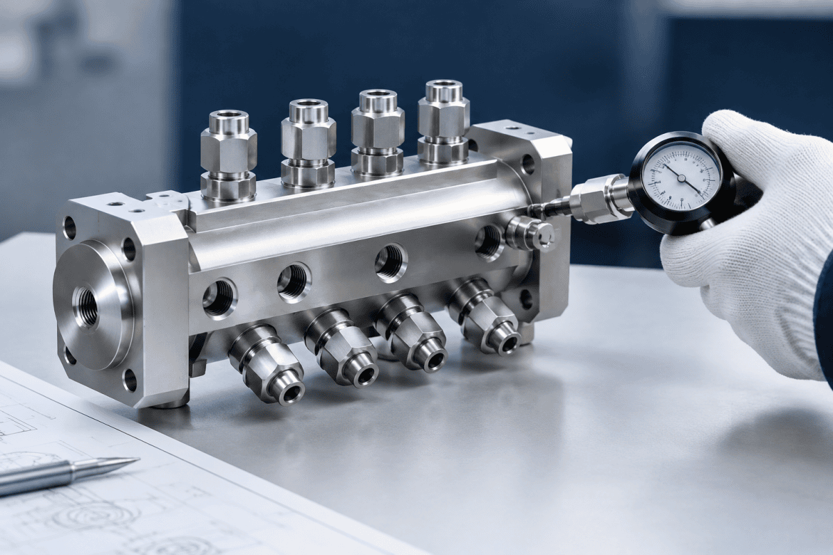
An OVD oxygen distribution manifold rarely gets attention until something drifts. It sits between the gas supply panel and the torch or burner array, splitting oxygen into multiple channels and delivering it at the flow rates and pressures each burner position requires. On an outside vapor deposition line, the OVD oxygen distribution manifold is the component that turns a single supply feed into repeatable, position-specific flow.
When it is machined accurately and its connections are verified before installation, the deposition process tends to behave predictably. When it is not, engineers often find themselves chasing flame instability, uneven soot deposition, or slow pressure decay that is difficult to trace back to a single fitting. This article covers the function of an OVD oxygen distribution manifold, what matters in custom machining, and how to verify connections so a replacement or new manifold does not introduce new variables into an outside vapor deposition process.
What the OVD Oxygen Distribution Manifold Does
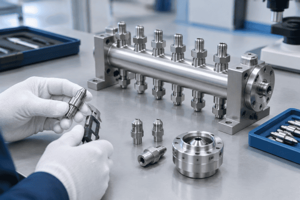
The OVD oxygen distribution manifold is a multi-port gas routing component. In a typical OVD setup, oxygen is used both as a carrier gas and as a reactant, and it must be split among several torch or burner positions along the deposition lathe. The manifold receives a single supply feed and divides it into discrete outlet channels, each of which may require a specific orifice size, internal passage geometry, and connection type.
Unlike a simple pipe tee, a properly machined OVD oxygen distribution manifold is designed so that flow through each outlet is repeatable and, where required, balanced.
Internal passage diameter, passage length, bend geometry, and surface finish all influence how gas behaves as it moves from the inlet to each outlet. For preform equipment manifold applications, this matters because small differences in flow resistance between channels can translate into visible differences in flame shape or deposition rate at the preform surface.
A custom OVD oxygen distribution manifold may also incorporate additional functions: mounting features, sensor or gauge ports, purge connections, and sealing interfaces. Each of these adds machining requirements that must be captured in the drawing and verified after production.
Why Custom Machining Is Often Necessary
Off-the-shelf manifolds rarely match an existing OVD platform. Burner spacing, connection standards, cabinet layouts, and gas panel interfaces vary between equipment generations and between fiber producers who have modified their lines over time. An OVD oxygen distribution manifold built for one configuration may not fit another, even if the general function is the same.
Drawing-based production versus reverse engineering
When original drawings are available, custom machining of an OVD oxygen distribution manifold is relatively straightforward: the part is produced to the stated dimensions, materials, and connection specifications. When drawings are missing or incomplete, reverse engineering becomes necessary. This involves measuring the existing part, identifying thread types and sealing surfaces, and documenting internal passage geometry that may not be directly visible.
For reverse-engineered manifolds, the critical output is a drawing set that both the machine shop and the end user can agree on before production. This reduces the risk of a part that fits mechanically but behaves differently in service. Suppliers who offer custom OVD and VAD burner sourcing and reverse engineering typically structure their work around this drawing-first approach, so that dimensional and material decisions are documented rather than assumed.
Material selection for manifold bodies
Manifold material depends on the component’s function, temperature exposure, chemical environment, and the engineering requirements of the specific OVD line. Stainless steel grades are common where corrosion resistance and structural stability are needed. Aluminum may be appropriate for certain mounting or structural components where weight and thermal behavior are acceptable, though it is not a universal substitute for stainless in oxygen service.
The choice should be made against the drawing, the gas compatibility requirements, and the operating conditions — not by category alone. Where aluminum components are specified, they are typically produced and inspected to the same drawing discipline as stainless parts. Aluminum OVD parts are one example of how material selection follows function rather than convenience.
Key Machining Considerations for an OVD Oxygen Manifold
Several design and production details determine whether a custom OVD oxygen distribution manifold will perform as intended. The most important ones are internal geometry, port location, threads, and sealing surfaces.
Internal passage geometry
The internal bores of the OVD oxygen distribution manifold determine how oxygen moves from the inlet to each outlet. Sharp internal corners, abrupt diameter changes, and rough bore finishes can create turbulence and inconsistent flow between channels. A well-machined manifold uses smooth transitions, consistent bore diameters where the design calls for them, and controlled surface finish inside the passages.
Because internal geometry is difficult to inspect after assembly, it should be verified at the machining stage. This is one reason manifold production benefits from a stable, documented process rather than one-off improvisation.
Port location and orientation
Port positions must match the mating components — the gas panel on the inlet side and the torch or burner connections on the outlet side. Angular orientation errors that seem small on a drawing can become significant when the OVD oxygen distribution manifold is installed in a confined cabinet. Verifying port location and orientation against the drawing before shipment is a basic but important step.
Threads and sealing surfaces
Thread type, pitch, and sealing method (face seal, O-ring, gasket, or conical seal) must be confirmed against the mating hardware. Mixed or misidentified thread standards are a common source of leaks and cross-threading during installation. Sealing surfaces on an OVD oxygen distribution manifold should be flat, free of tool marks, and finished to the specification on the drawing.
Mounting and structural features
Mounting hole patterns, bracket interfaces, and any structural reinforcement should be machined to the drawing so that the OVD oxygen distribution manifold can be installed without forcing or shimming. For OVD lines where the manifold is mounted near the torch area, thermal expansion and vibration should be considered in the mounting design.
Because the manifold often sits close to the burner array, engineers evaluating adjacent components may also review the OVD burner faceplate hole geometry and inspection steps as part of the same interface review.
Connection Verification Before Installation
Machining accuracy does not guarantee a leak-free installation. Connection verification is a separate step, and it should be performed on the bench before the OVD oxygen distribution manifold is installed in the gas system. The following checks are general practice and should be adapted to the specific equipment documentation and site procedures.
- Visual inspection of threads and seals. Check for burrs, debris, or damaged sealing surfaces. Any foreign material in an oxygen passage should be removed using methods consistent with oxygen-clean handling procedures.
- Thread engagement check. Confirm that mating fittings thread in smoothly by hand before any torque is applied. Forced engagement usually indicates a thread mismatch.
- Dimensional verification. Measure port spacing, face-to-face dimensions, and mounting hole positions against the drawing. This catches machining errors before they become installation problems.
- Pressure or leak test. Follow the equipment manufacturer’s procedures and site safety requirements for pressure testing. The method, test pressure, and acceptance criteria should come from approved documentation, not from general assumptions.
- Flow verification where required. If the OVD oxygen distribution manifold is designed to balance flow across outlets, a flow check may be appropriate before installation. The test method should be defined by the process engineer.
Each of these steps produces information. If a check fails, the cause is identifiable — a dimensional error, a thread mismatch, a damaged seal face, or an assembly issue — rather than an unexplained leak after installation.
Where connection problems tend to surface
In practice, most connection issues on an OVD oxygen distribution manifold appear at the outlet ports that mate with the torch or burner assembly, and at the inlet port that mates with the gas panel. These are the joints that see the most handling during installation and the most thermal cycling during operation.
For burner-side interfaces, the fit between the manifold outlet and the torch inlet is worth checking against the torch drawing, not just the manifold drawing. Related guidance on auxiliary tail burner replacement and interface checks covers similar mating-surface verification steps, and the same logic applies to any manifold-to-torch connection.
Documenting verification results
Recording the outcome of each check on an OVD oxygen distribution manifold creates a reference for future maintenance. A simple verification record — port dimensions, thread engagement notes, leak test results, and flow readings where applicable — shortens the next replacement cycle and gives maintenance teams a baseline if performance changes later.
The record should also note the cleaning method used and the ambient conditions during testing, since temperature and humidity can influence some leak-test methods.
Common Issues and How to Approach Them
When an OVD line shows symptoms that could involve the manifold, the goal is to distinguish possible causes from confirmed diagnoses. Several symptoms are often attributed to the OVD oxygen distribution manifold, but not all of them originate there.
- Uneven flame or deposition across burner positions. Possible causes include manifold flow imbalance, partially restricted passages, or a problem at the burner itself. Verification involves comparing flow or pressure at each outlet and inspecting burner components separately.
- Pressure drift during a run. This can originate from the manifold, a regulator, a leaking connection, or a change elsewhere in the gas system. A staged leak check and flow comparison helps localize the source.
- Leak at a manifold connection. Often a sealing surface or thread engagement issue rather than a manifold body defect. Inspect the specific joint before replacing the OVD oxygen distribution manifold.
- Contamination in the oxygen path. Can come from the supply, the manifold, or downstream components. Sampling and inspection at multiple points helps identify the origin.
For issues that involve burner behavior rather than the manifold, related technical articles such as the discussion of pressure balancing and gas flow dynamics in multi-channel OVD and VAD torches and the analysis of refractive index profile drift and burner concentricity can help separate manifold-related causes from torch-related ones.
Diagnostic sequence for suspected manifold faults
A structured diagnostic sequence reduces the chance of replacing an OVD oxygen distribution manifold that was not the actual source of the problem. Start by confirming the symptom — which burner position, which gas channel, and whether the deviation is constant or intermittent. Then compare outlet pressures or flows across all channels at a controlled supply condition.
If one outlet deviates, inspect the corresponding passage and connection. If all outlets deviate together, the cause is more likely upstream: supply pressure, regulator behavior, or a shared inlet connection. This split — single-channel versus all-channel — is often the fastest way to narrow the search before any component is removed.
Preparing a Sourcing Request for a Custom Manifold
A clear sourcing request shortens the path from inquiry to usable part. For a custom OVD oxygen distribution manifold, the following information is typically needed:
- Drawings or sketches, including port locations, internal passage geometry, and mounting features
- Dimensions and tolerances for all critical interfaces
- Connection types, thread standards, and sealing methods for inlet and outlet ports
- Material requirements and any surface finish or cleaning specifications
- Operating conditions: gas type, temperature range, and pressure range
- Quantity and whether the part is a one-time replacement or a recurring need
If drawings are not available, providing the existing part for measurement or clear photographs with dimensions can support reverse engineering. The more information provided upfront, the fewer assumptions enter the production process for the new OVD oxygen distribution manifold.
For readers also reviewing related components, the broader range of OVD burner parts and torch components often needs to be evaluated alongside the manifold.
Specification details worth documenting
Beyond the basic list, a few specification details are worth writing down explicitly for any custom OVD oxygen distribution manifold. Recording the surface finish requirement for sealing faces, the maximum allowable leak rate, and the cleaning or oxygen-compatibility standard to be applied will remove ambiguity during production.
Documenting the reference dimensions used for reverse engineering is also useful. If a future replacement OVD oxygen distribution manifold is needed, the earlier drawing set becomes the starting point rather than a new measurement exercise.
Where manifolds are part of a larger multi-channel torch assembly, it also helps to confirm that the manifold outlet count and spacing match the current torch configuration. Related work on machining multi-channel OVD burner bodies addresses the matching side of that interface.
Questions to resolve before the drawing is approved
A short review before drawing approval can prevent most downstream surprises on an OVD oxygen distribution manifold. Confirm that the outlet count matches the current torch or burner configuration, that thread standards on both inlet and outlet sides are stated explicitly, and that any sensor or purge ports are included in the port schedule.
It is also worth confirming who will perform the final inspection and what acceptance criteria apply. When those points are settled before machining begins, the production stage tends to run without clarification delays.
Material and Cleanliness Considerations in More Detail
Oxygen service places additional demands on any component in the gas path. The OVD oxygen distribution manifold is not exempt from those demands simply because it is upstream of the torch. Standard industry guidance on oxygen system design, such as the EIGA oxygen pipeline systems guidance, is a useful reference for material compatibility, cleanliness, and ignition-risk considerations.
Stainless steel remains the default for oxygen-wetted passages in most OVD installations. The exact grade should follow the drawing and the site standard. Where aluminum is used on mounting or structural components, it is generally kept out of the oxygen-wetted path unless the application specifically allows it.
Cleanliness matters because contamination in the oxygen path can affect deposition chemistry and, in some circumstances, create a safety concern. Bench inspection and clean handling procedures after machining reduce that risk on an OVD oxygen distribution manifold before it is installed.
Practical cleanliness steps include capping all ports immediately after machining, storing the part in clean packaging, and re-inspecting sealing faces just before installation. These are simple actions, but they prevent the kind of contamination that is difficult to remove once the manifold is in service.
FAQ
Can an OVD oxygen distribution manifold be made without original drawings?
Yes, through reverse engineering. The existing part is measured, thread types and sealing surfaces are identified, and internal geometry is documented as far as practical. A drawing is produced and reviewed before machining begins. Some internal features may require assumptions, which should be clearly noted on the drawing.
How do I know if the manifold material is suitable for oxygen service?
Material suitability depends on the component’s function, temperature exposure, chemical environment, and the engineering requirements of the system. Oxygen service has specific compatibility and cleanliness considerations. The material decision for an OVD oxygen distribution manifold should be made against the drawing and the applicable site and equipment requirements, not by material category alone.
What should be checked first if a new manifold leaks after installation?
Inspect the specific leaking joint: thread engagement, sealing surface condition, and whether the correct sealing method was used. A bench leak check before installation would have caught most joint-related issues. If the joint is correct and the leak persists, the manifold body or a passage may need inspection.
Can an OVD oxygen distribution manifold be modified rather than replaced?
In some cases, yes — for example, changing a port or adding a mounting feature. Modification requires the same drawing discipline as new production. Whether modification is appropriate depends on the material, the existing geometry, and the requirements of the application. It is usually evaluated case by case.
How long does a custom manifold typically take to produce?
Lead time depends on whether drawings exist, whether reverse engineering is required, the material selected, and the finishing and inspection steps. Once the drawing is approved, the machining stage itself is usually the shorter part of the schedule. Providing complete information upfront is the most reliable way to shorten the overall timeline.
Next Step
If you are evaluating a replacement or a new OVD oxygen distribution manifold, the most useful starting point is a drawing or a set of measured dimensions with connection details and operating conditions. Providing these with your inquiry allows the machining requirements and material selection to be reviewed against your application before production. To discuss a specific OVD oxygen distribution manifold, you can use our contact page to share your drawing, dimensions, and requirements for review and quotation.
