
Knowledge
OVD Auxiliary Tail Burner Replacement: Drawings and Interface Checks
Oct
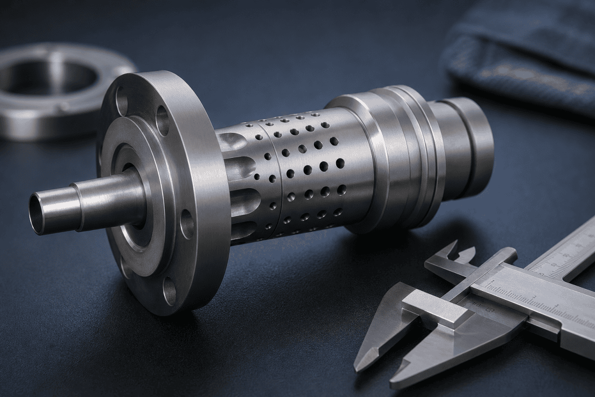
An OVD auxiliary tail burner replacement rarely fails for a single obvious reason. In most cases, the burner has drifted out of alignment, its faceplate has accumulated soot, its oxygen distribution has become uneven, or the replacement part simply does not match the original interface closely enough. Because the tail burner works at the end of the preform where the soot body is most vulnerable to thermal stress, small dimensional errors can create visible defects long before the burner itself looks worn. This article focuses on what to check before ordering a replacement, how to read a burner drawing, and which interface details matter most during installation.
Why an OVD Auxiliary Tail Burner Replacement Deserves Its Own Plan
In an OVD lathe, the auxiliary tail burner is not a duplicate of the main deposition burner. It typically runs at a different standoff, covers a smaller area, and is positioned to manage heat at the tail end of the growing preform. That difference in duty means it should be treated as a separate maintenance item with its own inspection criteria, spare-part documentation, and replacement interval.
When the tail burner is neglected, the consequences tend to appear at the ends of the preform rather than in the middle. Engineers often notice end-taper cracking, uneven soot consolidation, or a tail region that no longer matches the expected geometry. If you are troubleshooting that region, the review of preform end-taper thermal stress and burner head replacement provides useful background on how heat distribution at the ends affects the final body.
Replacement planning should start with the premise that the tail burner is a precision assembly. It is not enough to specify a generic multi-channel torch. The drawing, gas interface, mounting geometry, and faceplate condition all need to be verified before the part is ordered. Approaching the OVD auxiliary tail burner replacement as a defined project, rather than an emergency parts order, keeps the verification steps from being skipped under schedule pressure.
Reading an Auxiliary Tail Burner Drawing Correctly
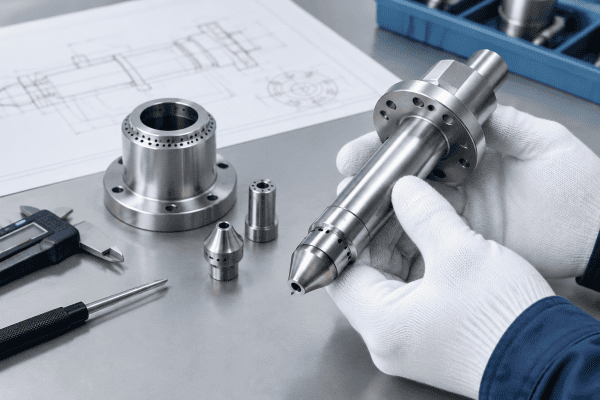
A burner drawing communicates more than overall length. For replacement purposes, the useful drawing is the one that defines the features which control fit and gas delivery. When you request a quotation, organize the information into the categories below.
Dimensional features to confirm
- Overall length and insertion depth: Determines how the burner sits in its holder and where the tip sits relative to the preform. A few millimeters of error can change the effective standoff.
- Mounting flange or thread geometry: Pitch, diameter, and flange thickness must match the holder. A thread that engages but bottoms out early can leave the tip at the wrong depth.
- Nozzle array layout: Number of channels, hole spacing, and hole diameter distribution. These affect flame shape and heat coverage at the tail.
- Faceplate profile: Flat, stepped, or contoured. The profile influences how the flame attaches and how soot accumulates.
- Concentricity and runout: Particularly important where the burner is expected to produce a symmetric heat pattern.
If the original drawing is incomplete, a dimensional inspection of the removed part can reconstruct the critical features. This is a normal part of reverse engineering for optical fiber equipment, and it is worth documenting before the old part is discarded. The details captured at this stage become the acceptance criteria for the OVD auxiliary tail burner replacement.
Gas interface and connection details
The gas interface is where many replacement projects encounter problems. Record the following for each channel:
- Connection type (compression fitting, threaded port, flange, or manifold-mounted)
- Port size and thread specification
- Sealing method (gasket, O-ring, metal-to-metal, or welded joint)
- Number of independent gas paths and their arrangement
- Whether the burner mounts directly to a manifold or connects through flexible lines
If the tail burner mounts on an oxygen distribution manifold, confirm the port pattern and sealing surfaces on both sides. The OVD auxiliary tail burner and oxygen distribution manifold is an example of a component where the interface, not just the burner, determines whether the replacement will seal and flow correctly.
It is also worth noting that a successful OVD auxiliary tail burner replacement depends on confirming both halves of every connection: the burner side and the equipment side. A manifold that has been modified since the original drawing was issued can invalidate an otherwise correct burner drawing, so update the interface documentation whenever upstream hardware changes.
Interface Checks Before and After an OVD Auxiliary Tail Burner Replacement
Interface checks are the practical bridge between the drawing and the running process. They should be performed on the removed part, on the new part, and on the mating equipment. Treating these checks as a fixed checklist rather than an informal inspection is what keeps an OVD auxiliary tail burner replacement from becoming a repeat maintenance event.
Before installation
- Verify the mounting interface. Check thread condition, flange flatness, and holder wear. A worn holder can misalign a new burner even if the burner itself is accurate.
- Compare nozzle positions. Use the drawing to confirm hole count, spacing, and orientation. Rotational orientation matters when the nozzle pattern is not symmetric.
- Inspect sealing surfaces. Look for scratches, corrosion, or deformation on both the burner and the manifold. Sealing defects often mimic gas-flow problems.
- Check for contamination. Protective caps, machining residue, or handling dust can block small channels. Clean according to your equipment documentation before installation.
- Confirm part identification. Match the replacement to the original by drawing number, revision, and material, not by appearance alone.
After installation
- Leak-check the gas connections using your site’s approved procedure. Do not rely on visual inspection alone.
- Confirm the tip position relative to the preform using the same reference used before removal. If the old position was not recorded, establish a baseline before running production.
- Check flame symmetry at low output before bringing the burner to operating conditions. A tilted or asymmetric flame can indicate misalignment or a partially blocked channel.
- Monitor the tail region across the first few preforms. Changes in end taper, soot density, or surface condition are early indicators that the interface is not correct.
For broader guidance on symmetrical flame behavior and its causes, the article on burner flame tilt explains how mounting and channel issues can affect flame direction. A follow-up verification after the first production run, compared against the baseline recorded before the OVD auxiliary tail burner replacement, will confirm that the installation is stable.
Common Reasons an OVD Auxiliary Tail Burner Replacement Does Not Solve the Problem
Replacing the burner is sometimes the right step, but not every tail-end defect is caused by the burner. Distinguishing burner-related causes from process or equipment causes prevents unnecessary parts spending and repeat maintenance.
- Soot clogging on the faceplate: If the old burner shows heavy deposit, the replacement may clog at a similar rate. Review faceplate condition and cleaning practice. The article on OVD burner faceplate replacement and hole geometry covers this pattern.
- Manifold or distribution imbalance: If gas delivery upstream is uneven, a new burner will reproduce the same asymmetry.
- Holder or mount wear: A loose or worn holder changes the effective tip position. This is an equipment issue, not a burner issue.
- Incorrect material selection: A burner used at the tail may see different thermal and chemical exposure than a main deposition burner. Material suitability depends on the component’s function, temperature exposure, and the surrounding environment.
- Process setpoint drift: Changes in other lathe parameters can shift the heat balance at the tail independently of burner condition. Reviewing refractive index profile drift and burner concentricity data alongside burner records helps separate process causes from hardware causes.
None of these causes can be confirmed from a single observation. Use a structured approach: document the defect, compare it against the burner drawing and interface records, and change one variable at a time. This discipline also makes it easier to decide whether a second OVD auxiliary tail burner replacement is justified or whether the root cause lies elsewhere on the lathe.
Material and Fabrication Considerations for Replacement Parts
Auxiliary burner components are often specified in materials selected for thermal stability, oxidation resistance, and compatibility with the gases used. The correct choice depends on where the component sits in the assembly. A faceplate exposed directly to the flame has different requirements than a mounting body or a manifold block.
When discussing a replacement with a supplier, describe the function of the part, the expected thermal environment, and any cleaning or handling chemicals it will contact. Avoid specifying a material purely because a similar part was once made from it. If the original material is unknown, a reverse-engineering review can help identify suitable candidates based on the application rather than guesswork. For an OVD auxiliary tail burner replacement, the material review should cover every wetted and heated surface, not just the tip.
For non-standard geometry or obsolete parts, drawing-based manufacturing is often more practical than searching for a catalog equivalent. The guide to sourcing custom OVD and VAD burners outlines how the material science and reverse-engineering process works for fiber preform engineers, and it is a useful reference when the drawing package is incomplete.
How corrosion and high-temperature alloys behave is documented in resources from organizations such as the National Institute of Standards and Technology (NIST) materials data portal, which publishes materials data that can help engineers reason about alloy performance in demanding environments.
Preparing a Clear Replacement Request
A well-prepared request reduces back-and-forth and lowers the risk of receiving a part that fits poorly. Include the following in your inquiry:
- Original drawing number and revision, if available
- Dimensional sketch or measured drawing of the removed part
- Photographs of the burner, faceplate, and mounting interface
- Gas connection details for each channel
- Material information, or a description of the operating environment if unknown
- Quantity required and whether the part is a one-time replacement or a recurring spare
If the tail burner is part of a larger assembly, indicate which components are being replaced and which are being reused. This helps the supplier check interface compatibility across the whole group rather than only the burner body. A clear request also shortens the lead time for an OVD auxiliary tail burner replacement when the line is already down.
When the request concerns a custom nozzle configuration rather than a standard body, confirm the specifications before ordering. The checklist for custom OVD burner nozzle replacement covers the key points that should be agreed in writing.
Documentation and Spares Strategy
Once an OVD auxiliary tail burner replacement has been completed successfully, capture what was learned. Record the as-found dimensions, the as-installed tip position, the leak-test result, and the first-run observations. This record becomes the baseline for the next replacement and reduces the time needed to verify a new part.
A practical spares strategy keeps at least one verified spare on site, with its drawing package and interface checklist stored alongside it. Because tail burner geometry can vary between OVD lines, spares should be labeled against the specific equipment rather than pooled by appearance. Reviewing tail-end defects alongside process data, such as refractive index profile drift, also helps confirm whether an OVD auxiliary tail burner replacement addressed the true cause.
FAQ
Can I replace only the auxiliary tail burner without replacing the manifold?
Often yes, but the decision depends on the condition of the manifold sealing surfaces, port threads, and internal channels. Inspect both sides of the interface before deciding. If the manifold shows corrosion, deformation, or blocked passages, replacing only the burner may not restore correct gas distribution.
How do I know whether the tail burner or the process settings caused a defect?
Start with documentation. Record the defect location and appearance, inspect the burner faceplate and nozzle channels, and compare the burner’s installed position against the drawing. If the burner and interface are within specification, review upstream gas delivery, holder condition, and process parameters with qualified personnel before changing setpoints.
What if the original drawing is no longer available?
A dimensional inspection of the removed part can reconstruct the critical features needed for manufacturing. Concentrate on mounting geometry, nozzle layout, gas ports, and overall length. A supplier experienced in reverse engineering can work from measurements and photographs, but the more complete the data, the lower the risk of a mismatch.
Are auxiliary tail burners from different OVD lines interchangeable?
Not automatically. Even within the same process family, tail burners may differ in nozzle layout, mounting, gas interface, and material. Interchangeability should be verified against the specific drawing, dimensions, gas connections, and application requirements of the equipment in question.
Process Context and Cross-Process Comparison
Tail burner behavior is easier to interpret when it is placed in the wider context of preform deposition practice. The comparison of OVD, VAD, and MCVD torch nozzle designs explains how nozzle geometry and gas delivery conventions differ between processes, which is useful when a team is transferring experience from one line to another. Burners that look similar on the outside may have very different internal channel arrangements, and that difference shows up in flame shape and heat coverage.
Within the OVD family, the auxiliary tail burner usually carries a lighter thermal duty than the main deposition burner, but it operates in a region where the soot body has less mechanical support. This is why interface precision matters as much as raw thermal output. A verified OVD auxiliary tail burner replacement restores the intended heat profile at the tail, but only if the mounting position and gas delivery match the drawing conditions assumed during process development.
From a maintenance planning perspective, it also helps to treat the tail burner as part of a small assembly rather than an isolated torch. The holder, manifold, sealing hardware, and gas lines all influence the final result. When any of those elements is modified, the working drawing set should be updated so the next OVD auxiliary tail burner replacement starts from accurate documentation instead of assumptions.
Acceptance Criteria and Verification Records
A replacement is not complete until it has been verified against defined acceptance criteria. Writing those criteria down before the work begins keeps the verification objective and repeatable. Typical criteria for an auxiliary tail burner include dimensional conformance to the drawing, correct installation depth and rotational orientation, leak-free gas connections, and a symmetric flame at low and operating output.
Verification records should capture what was measured, not only whether the result was acceptable. Recording the as-installed tip position, the leak-test readings, and the observed flame condition creates a trail that can be compared with the next OVD auxiliary tail burner replacement. Over time, that trail reveals whether tail-end problems follow the burner, the holder, or the process, which is difficult to judge from a single event.
For teams running multiple OVD lines, a shared record structure is more useful than separate local notes. Standard fields for drawing revision, material, gas connection type, and first-run observations allow engineers to compare components across lines without translating between formats. When a recurring tail-end defect appears on more than one line, consistent records make the pattern visible earlier and shorten the diagnostic path.
Next Step for Your OVD Auxiliary Tail Burner Replacement
If you are planning an OVD auxiliary tail burner replacement, gather the drawing, dimensional data, gas interface details, and photographs of the removed part before contacting a supplier. OVDParts can review these inputs against your application and discuss standard or custom burner components, including drawing-based production for non-standard geometry. Documenting acceptance criteria in advance also gives the supplier a clear target for both dimensions and interface performance. To move forward, contact our team with your component requirements and operating conditions for a quotation. A disciplined OVD auxiliary tail burner replacement process, supported by accurate drawings and complete interface records, is the most reliable way to keep tail-end deposition stable.
