
Knowledge
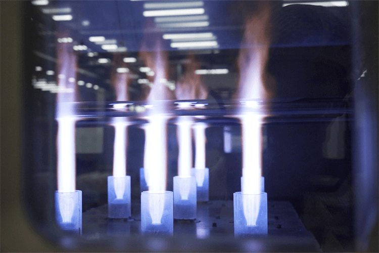
Why OVD Burner Flames Tilt: Orifice Degradation, Chemical Erosion, and How Alloy Selection Restores Deposition Stability
Sep
In Outside Vapor Deposition (OVD), few occurrences disrupt a production run faster than flame deflection. When a multi-stream deposition torch begins to bias its flame pattern off-axis, the consequences on the rotating preform target rod are immediate: asymmetrical soot boule growth, uneven density profiles, and irreversible core rod refractive index drift.
Diagnosing flame tilting requires looking past basic gas flow controller calibrations and examining the microscopic degradation happening at the torch faceplate.
The Anatomy of Flame Deflection: What Happens at the Nozzle Tip
An OVD torch functions by feeding alternating annular or multi-orifice streams of combustible gases (H₂/O₂) alongside halide precursors (SiC₄ and GeCl₄). The primary chemical reaction at the flame front produces silica soot and gaseous hydrochloric acid:
Under normal parameters, laminar gas boundaries isolate the metal faceplate from peak reaction temperatures. Over prolonged deposition campaigns, three distinct failure mechanisms compromise this boundary:
-
Micro-Pitting from Chloride Condensation: During shutdown cycles or minor line pressure drops, trace amounts of unreacted precursor hydrolyze directly on cooling metal surfaces, forming corrosive acid residues that pit micro-channel walls.
-
Thermal Creep at Annular Margins: The extreme radiant heat from the growing silica boule induces thermal stress gradients between the inner chemical feed tubes and outer oxygen curtains.
-
Localized Silica Bridging: Pitted or rough channel exits alter localized boundary layer velocity, causing silica soot particles to cling to the rim, physically skewing the exit gas angle.
Normal Flow Boundary:
[ Gas Channel ] ─── Smooth Laminar Flow ───> Symmetrical Flame Geometry

Degraded Orifice Rim:
[ Pitted Wall ] ─── Micro-Turbulence / Drag ─> Asymmetrical Jet Vector (Flame Tilt)
Material Performance Under Extreme OVD Atmospheres
Material selection determines how long an orifice retains its concentricity before flow velocity vectors begin to wander.
| Engineering Parameter | Standard 6000-Series Aluminum | 316L Stainless Steel | Grade 5 Titanium Alloy |
| Operating Thermal Limit | Low (softens under prolonged soak) | Medium-High | High (maintains channel rigidity) |
| Acidic Chloride Resistance | Vulnerable to micro-pitting | Moderate | Exceptional (self-passivating TiO₂ |
| Thermal Expansion Match | High expansion coefficient | Moderate expansion | Low thermal distortion |
| Typical Failure Mode | Tip erosion & annular widening | Channel warping / heat scaling | Gradual uniform surface wear |
While precision-machined aluminum provides adequate heat dissipation and low upfront procurement costs for standard runs, it shows wear quickly when pushed through extended heavy-core deposition recipes.
Switching critical multi-stream nozzles to high-grade Titanium alloy eliminates surface softening, preventing the localized flow resistance that causes early flame deflection.
Mechanical Integrity: Concentricity and Channel Micro-Finish
A torch made from the right alloy will still tilt if its machining introduces baseline flow imbalance.
Multi-stream burner nozzles rely on concentric gas delivery. Any tool deflection during internal micro-drilling creates rough surfaces inside the channel. Even microscopic burrs generate uneven drag across the circumference of the jet, prompting the gas stream to lean toward the path of lower resistance as it exits into atmospheric pressure.
High-stability deposition torches require single-clamping production on multi-axis CNC turn-mill machining centers. Machining both internal gas chambers and exterior locating registers in one continuous sequence eliminates the cumulative runout errors typical of separate lathe and mill operations.
Shop-Floor Diagnostics and Corrective Actions
Before pulling a torch off the deposition lathe, run through this progressive verification checklist:
-
Check Static Backpressure Consistency: Connect inert nitrogen to individual gas rings at identical regulator settings. A discrepancy in backpressure between opposing quadrants indicates partial orifice clogging or channel narrowing.
-
Inspect the Nozzle Faceplate Under Magnification: Look closely at the inner precursor orifice edges. If irregular beveling, white silica crusting, or micro-pitting appears on one side of a discharge port, the nozzle has suffered chemical erosion and cannot be salvaged through superficial cleaning.
-
Verify Peripheral Thermal Equilibrium: Flame tilting often intensifies when transitioning across the preform tail ends. In many configurations, pairing the primary torch with a dedicated OVD Auxiliary Tail Burner & Oxygen Distribution Manifold stabilizes regional thermal gradients, shielding the primary nozzle from abrupt thermal shock at the stroke ends.
Upgrading Your Preform Deposition Hardware
Eliminating line shutdowns from flame distortion comes down to reliable tooling and durable materials. Replacing worn aluminum nozzles with field-tested Titanium OVD Burner Assemblies stabilizes flame geometry across long campaigns, maintaining radial symmetry without frequent cleanroom recalibration.
If your facility requires standard replacement parts or custom make-to-print tooling, explore our full catalog of in-stock OVD burner components, or submit your technical CAD drawings to our engineering team for a full manufacturability review.
