
Knowledge
Optical Fiber Winder Shafts and Sleeves: Drawing-Based Replacement Sourcing
Oct
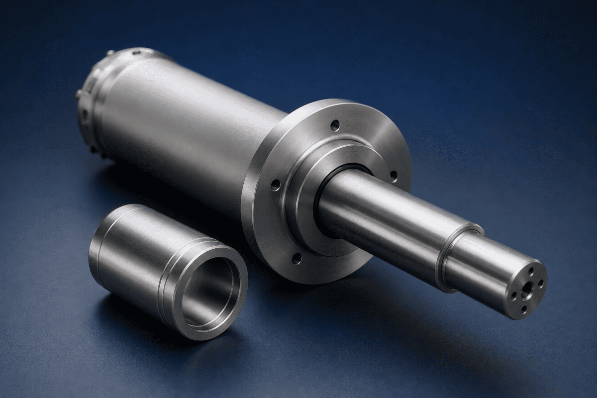
When optical fiber winder shafts begin to wear, the first signs often appear in the wound package rather than at the machine: slight tension drift, layer irregularity, or a subtle wobble that grows over time. Fiber winding is one of the quieter determinants of finished fiber quality. Slight shaft runout, a worn sleeve bore, or a mismatched taper can show up much later as uneven tension, layer irregularity on the bobbin, or damage at the fiber surface during take-up. For maintenance and purchasing teams, the practical challenge is that optical fiber winder shafts and their sleeves are often older, lightly documented, and difficult to replace with standard catalog parts. Drawing-based replacement sourcing — manufacturing a new shaft or sleeve from measured geometry and documented operating conditions — is often the most reliable route. This article explains what to inspect, how to specify the part, and what to ask a supplier, with reference to OVDParts custom manufacturing capabilities where relevant.
Why Optical Fiber Winder Shafts and Sleeves Wear Differently
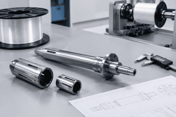
The winder shaft transmits rotation to the bobbin or reel and maintains the fiber’s running position during take-up. The sleeve is the interface between the shaft and the bobbin — it may be a slip fit, a taper fit, or an expanding element depending on the machine design. These two components fail for different reasons, and that distinction matters when writing a replacement specification for optical fiber winder shafts.
Shafts tend to fail at high-stress locations: drive-end journals, bearing seats, keyways, taper transitions, and set-screw contact zones. Symptoms include visible fretting, journal diameter loss, scoring, or detectable runout when the shaft is turned in its own bearings.
Sleeves more often fail through internal wear from repeated bobbin mounting, distortion after heat or mechanical abuse, and loss of concentricity between the bore and the outer running surface. Because the two parts are usually made from different materials and heat treatments, “the winder is old” is not a sufficient replacement rationale. Each component needs its own inspection record and its own specification.
Common Winding Problems That Point Back to Optical Fiber Winder Shafts or Sleeves
Not every winding defect originates at the shaft. But several recurring issues merit a shaft and sleeve check before other causes are pursued.
- Progressive runout: If wound packages show increasing axial wobble over time, the cause may be a shaft that has bent slightly, a worn bearing seat, or a sleeve that no longer centers on the shaft.
- Uneven traverse or pitch variation: This is often a control or guide issue, but optical fiber winder shafts with abnormal radial runout can interact with the traverse system and produce inconsistent winding pitch.
- Bobbin slip: If the bobbin rotates slightly relative to the shaft during tensioning, the sleeve fit or clamping mechanism may be worn.
- Fiber damage at contact points: A damaged sleeve surface or a burr on a shaft shoulder can abrade fiber that passes near it during start-up or shutdown.
- Vibration under load: Worn journals or a loose sleeve fit can introduce periodic vibration that shows up in the wound package rather than at idle.
Because several of these symptoms overlap with drive, bearing, and tension-control problems, document the symptom with timing and operating conditions before assuming the shaft is at fault.
Inspection Procedure Before Replacement Sourcing
Measure the shaft in its own bearings
Runout should be measured in the machine, with the shaft supported as it is in normal operation. Measuring a shaft on a bench without its bearing supports can produce misleading numbers. Record radial runout at several points along the length and axial runout at each end.
Record all functional diameters and fits
Measure bearing seats, drive coupling interfaces, sleeve mounting diameters, keyway dimensions, and any taper angles. Note the fit class where the original drawing is available; where it is not, measure a known-good companion part rather than guessing. A taper measured on a worn sleeve may not represent the intended angle.
Check sleeve bore and outer surface separately
For the sleeve, measure the bore diameter at multiple depths, the outer diameter or running surface, concentricity between bore and outer surface, and end-face squareness. If the sleeve has slots, expansion features, or clamping geometry, record those features with dimensions.
Document material and condition
Where hardness or material data exist, record them. Where they do not, note the operating environment — rotational speed range, tension load range, cleaning agents used, and any heat exposure — so a supplier can propose a suitable material. Do not infer material from appearance alone.
Look for secondary damage
Scoring on a shaft journal may indicate a bearing or housing problem that will damage a new shaft if not corrected. A replacement part will not fix a root cause that remains in the machine.
Why Winder Parts Are Rarely Catalog Items
Unlike burner nozzles or standard deposition components, optical fiber winder shafts and sleeves are typically specific to a machine platform, a bobbin format, and a winding process. Shaft length, diameter progression, taper geometry, bore details, drive coupling, and sleeve fit are rarely standardized across lines, and replacements are usually ordered by drawing or reverse-engineered from a sample.
This is a normal sourcing condition, not a problem. What it requires is a supplier who can work from measurement data, sketches, or physical samples rather than expecting a part number. The OEM/ODM machining services at OVDParts are structured for this kind of drawing-based and sample-based production, including non-standard winder hardware that does not appear in standard component catalogs.
If the winder is part of a broader component replacement effort, it may be worth reviewing the wider range of optical fiber equipment parts available, but shaft and sleeve work is usually handled as a separate custom project because of the measurement and fit requirements.
What Belongs in a Replacement Specification
A specification that a machine shop can quote from should contain, at minimum:
- General arrangement drawing or dimensioned sketch of the shaft and sleeve, including overall lengths, diameters, and step transitions.
- Fit requirements for bearing seats, drive coupling, and sleeve mounting — including whether the fit is press, slip, or taper, and the intended fit class if known.
- Concentricity and runout requirements referenced to a stated datum, not described qualitatively.
- Taper angle and gauge dimensions where tapered features exist, measured from a known-good reference if a drawing is unavailable.
- Surface finish requirements on running surfaces and sealing or clamping interfaces.
- Material and heat treatment where documented, or the operating conditions that will drive material selection if not.
- Balancing requirements if the shaft operates at higher rotational speeds.
- Quantity and lead-time context — a single replacement versus a stocked spare.
Where the original drawing does not exist, a physical sample with measured dimensions can be sent for reverse engineering. Clear marking of wear zones on the sample helps the supplier distinguish intended geometry from damage.
Material Selection for Shafts and Sleeves
There is no universal material for fiber winder hardware. Suitability depends on the function of the specific feature, the rotational and load conditions, the chemical environment during cleaning, and whether the part contacts fiber directly. For optical fiber winder shafts, material choice often balances wear resistance at the journals against toughness at keyways and steps.
- Steel grades with appropriate heat treatment are common for load-bearing shafts and wear-resistant journals. Hardness and toughness need to be balanced; a shaft that is too hard may chip at keyways or steps.
- Aluminum or lighter alloys may be appropriate where inertia, weight handling, or non-magnetic behavior matters, provided the running loads permit it. In the broader OVD component range, aluminum OVD parts illustrate how material choice is driven by function rather than by habit.
- Surface treatments such as hard chrome, nitriding, or coatings can improve wear resistance on journal and sleeve running surfaces, but they must be compatible with the base material and the surrounding fits.
- Non-metallic or coated interfaces may be chosen for sleeves where fiber contact or friction control is a concern, subject to dimensional stability under load and temperature.
Material decisions should be confirmed with a supplier who can review the operating conditions and the specific features of the part, not selected from a generic preference list.
Sourcing Questions to Ask Before Ordering
Ask a prospective supplier to confirm:
- Whether they can manufacture from drawings, sketches, or physical samples, and how they handle incomplete drawings.
- How they inspect incoming samples and verify dimensions before machining.
- What measurement equipment they use for runout and concentricity verification.
- How material and heat treatment choices are proposed and documented.
- Whether they can produce both the shaft and the matching sleeve as a set to preserve fit.
- What inspection documentation is provided with delivery.
These questions are especially important when replacing an older part on a machine whose drawings may no longer reflect the as-built configuration.
How Drawing-Based Sourcing Fits the Wider Winder System
Optical Fiber Winder Shafts rarely operate in isolation. They sit inside a winder subassembly that includes clamps, cutters, changeover components, and spool hubs. When a shaft or sleeve is replaced, it is worth checking the surrounding interfaces for wear that could affect the new part, or that the new part could affect in turn.
For example, the clamp that grips the shaft during operation may have lost grip or developed a burr. A guide to take-up winder clamp replacement covers dimensions and grip checks that pair well with a shaft inspection. Similarly, if the shaft is removed during a bobbin change, the bobbin changeover components — clamps, cutters, and related hardware — should be reviewed at the same time to avoid reinstalling a new shaft into a worn interface.
At the spool end, the spool hub bore and shaft interface determine how well the bobbin centers on the shaft. If the hub bore is worn, even a perfectly machined new shaft may not restore concentricity. Checking the hub at the same time as the shaft can prevent a repeat replacement.
In some lines, the winding section is part of a larger preform or draw process. The winder cutter assembly parts guide covers cutter and clamp replacement specifications that may share measurement data with the shaft project. For preform-related equipment, similar sourcing logic applies to Corning preform equipment parts, Sumitomo Electric preform equipment parts, and SG Controls preform replacement parts, where drawing-based sourcing is also standard.
Where a lathe or carriage is involved in the same production area, the SG Controls MCVD lathe spare parts guide shows how holders and carriage components are specified from drawings. The same measurement discipline applies to optical fiber winder shafts: record the geometry, note the fits, and describe the operating conditions.
Balancing, Runout, and Speed Considerations
As winding speeds increase, the tolerance budget for runout and balance tightens. A shaft that performed acceptably at low speed may show vibration at higher rpm if its residual imbalance or runout is marginal. When specifying optical fiber winder shafts, include the operating speed range and the acceptable vibration level if known.
Balance grade requirements should be stated on the drawing where the shaft operates above moderate speeds. If no grade is specified, a supplier may default to a general machining tolerance that is adequate for static operation but not for high-speed winding. For accuracy, ISO 1940-1 is a recognized reference for balance quality requirements of rigid rotors; see the ISO 1940-1 balance quality standard for the grade definitions that can be cited in a specification.
Runout should be referenced to a datum that reflects how the shaft is supported in the machine. If the datum is unclear, the supplier may measure from a convenient surface that does not match the machine’s actual axis of rotation.
Verification and Documentation at Delivery
When a new shaft or sleeve arrives, verification should match the specification that was sent. At minimum, check:
- Overall dimensions against the drawing or sketch.
- Functional diameters and fit classes at bearing seats, coupling interfaces, and sleeve mounting surfaces.
- Runout and concentricity readings, ideally with the same datum used in the specification.
- Surface finish on running and sealing surfaces.
- Material and heat treatment certificates where specified.
- Inspection records for taper angles and gauge dimensions.
If any measurement falls outside the specified tolerance, resolve it before installation. Installing a marginal part can damage the machine and complicate the supplier discussion afterward.
FAQ
Can I replace only the sleeve and keep the existing shaft?
Sometimes, but only if the shaft has been measured and confirmed to be within acceptable runout and journal condition. A new sleeve fitted to a worn shaft will not restore winding accuracy. Measure the shaft first, then decide whether to replace one part or both.
How do I handle a taper fit when the original drawing is missing?
Measure the taper angle and gauge dimensions against a known-good reference. If the sleeve and shaft have both worn, the as-measured taper may not be correct. In that case, work from the machine’s documented taper standard if one exists, or record the measured value and flag it as unverified in the specification.
Can the same supplier make the shaft and sleeve as a matched pair?
Yes, and this is often preferable. Producing both parts together allows the supplier to control the fit between them rather than matching a new part to an existing worn one. Provide both items or full dimensions for both when requesting a quotation.
What information is needed for a quotation on a custom winder shaft?
Drawings or a dimensioned sketch, measurement data on fits and concentricity, material and heat treatment requirements or operating conditions, and quantity. A physical sample speeds the process when drawings are not available.
Next Step
If optical fiber winder shafts or sleeves are due for replacement, gather the inspection data first: runout readings, functional diameters, taper dimensions, material notes, and operating conditions. Send drawings, sketches, measured samples, or the worn parts themselves to request a quotation from OVDParts. Include what the part does, how it mounts, and what is wearing so the manufacturing review can address the actual failure mode rather than only the geometry.
