
Knowledge
Optical Fiber Guide Roller Shafts: Precision Machining and Assembly Checks
Oct
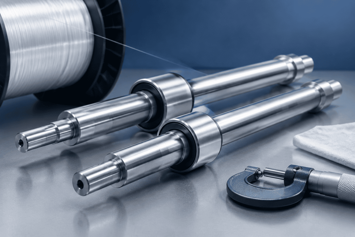
Optical Fiber Guide Roller Shafts are easy to overlook because they do not sit in the flame path or touch the glass at deposition temperature. In practice, however, optical fiber guide roller shafts define how glass fiber, coated fiber, or preform handling fixtures are supported, aligned, and rotated across winding, drawing, and take-up stations. If a shaft runs out of tolerance, seats poorly in its bearing, or mates badly with a roller body, the result shows up as fiber wander, uneven tension, or surface marks that are difficult to trace back to a single component.
This article looks at what matters when specifying optical fiber guide roller shafts, how they are precision machined, and what to check during assembly and after replacement.
What a Guide Roller Shaft Actually Does
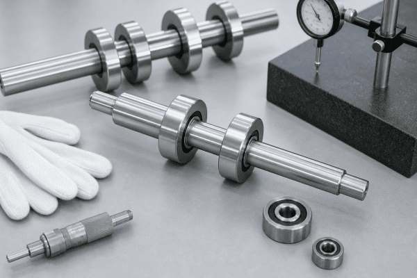
Optical Fiber Guide Roller Shafts serve as the structural and rotating interface between a roller body and the machine frame. Depending on the station, a guide roller shaft may be fixed rather than rotating, with the roller turning on bearings mounted around it, or it may rotate with the roller as part of a driven assembly. In fiber winding and take-up positions, the shaft must hold the roller in a stable axial position while allowing smooth, low-vibration rotation at the line speed the process requires.
Because the shaft couples several tolerances together, a small deviation can be amplified. Shaft straightness, journal diameter, shoulder squareness, keyway or flat position, thread quality, and surface finish all influence how the roller sits and spins. In a winding station, the roller face position affects where the fiber lays down; in a guide position, runout can bias the fiber path and change tension slightly from one side of the roller to the other.
These effects are usually cumulative, which is why shaft quality is judged during assembly rather than in isolation.
It also helps to separate the role of the shaft from the role of the roller itself. The roller controls contact geometry, surface condition, and friction against the fiber. The shaft controls position, alignment, and rotational stability. When a station develops a fault, the two are often blamed interchangeably, so a useful first step is to decide which function is actually failing before any part is removed.
Precision Machining Considerations for Optical Fiber Guide Roller Shafts
Material Selection Is Application-Driven
There is no single correct material for optical fiber guide roller shafts. The choice depends on load, speed, wear environment, corrosion exposure, weight limits, and whether the shaft is driven. Common options include stainless steels for corrosion resistance and cleanability, alloy steels for greater strength and wear resistance when heat treated, and aluminum alloys when lower rotating mass is important.
Material suitability should be confirmed against the component’s actual function and operating conditions rather than assumed from a broad product category. A shaft running near a coating or cleaning area may need different corrosion resistance than one in a dry, enclosed winder. Where aluminum components are used in adjacent hardware, similar logic applies to OVD aluminum parts used elsewhere in the machinery, though roller shaft requirements should be evaluated on their own terms.
Heat treatment and surface treatment decisions should be documented at the same time as the base material. Case hardening, nitriding, passivation, and coatings each change dimension slightly, so a specification that lists material without treatment can produce a part that fits on the bench and binds once installed. For corrosion-resistant shafts, passivation and cleaning requirements are often as important as the alloy choice.
Tolerances That Control Roller Behavior
The most influential machined features on optical fiber guide roller shafts are usually:
- Bearing journals. Diameter tolerance and roundness determine bearing fit and internal clearance. Too loose and the shaft can creep or fret; too tight and bearing preload rises, which increases heat and drag.
- Straightness. Bending along the shaft axis produces runout at the roller face, which translates to lateral fiber movement.
- Shoulder squareness. A shoulder that is not square to the axis pushes the roller or bearing slightly off-axis when clamped.
- Concentricity between journals. If the drive-side and roller-side journals are not concentric, the roller cannot run true even if each journal is individually within size.
- Surface finish. Journal finish affects bearing seating and wear; sealing surfaces and fiber-facing surfaces may have separate finish requirements.
Runout, not just diameter, is often the practical limit. A shaft can measure correctly on diameter and still cause visible roller wobble if total indicated runout is high.
Features That Affect Assembly
Optical Fiber Guide Roller Shafts usually carry retention features: shoulders, retaining ring grooves, threads, keyways, flats, or cross-drilled holes. Their position tolerance matters as much as their size. A keyway cut slightly off angular position will rotate the roller relative to its intended index, which matters in driven assemblies where roller timing or pitch is controlled. Threads used with locknuts need to be square to the axis; a thread that is radially off-center will tilt the nut and, in turn, the inner bearing race.
Small geometric details also drive cost and lead time. A chamfer or radius at a journal entry protects the bearing during installation, but an oversized lead-in reduces the effective seating length. Undercuts for thread relief must be sized so the mating nut seats fully against the shoulder. Specifying these features on the drawing prevents an otherwise accurate shaft from needing rework after delivery.
Assembly Checks Before the Line Starts
Good assembly practice catches most shaft-related problems before they reach production. The checks below are general and should be adapted to the specific station and equipment documentation.
Verify Cleanliness and Fit First
Inspect journals and mating bores for burrs, nicks, and residual debris from machining. Burrs on a journal can score a bearing during installation and create a false fit that changes after the burr breaks down. Dry-fit critical interfaces where possible to confirm that components seat by hand or with controlled press force, not by force alone.
Measure Runout After Assembly, Not Just Before
A shaft that runs true on the bench can show runout once the roller, bearings, and retaining hardware are installed. Mount the assembly in its support or in a suitable check fixture and indicate the roller face and the shaft extension. If runout appears only after assembly, the cause is often seating, contamination, or a non-square shoulder rather than the shaft itself. Distinguishing between these possibilities is the difference between a correct diagnosis and unnecessary replacement.
Check Axial Positioning and End Float
Confirm that the roller sits at the intended axial position and that bearings have the specified end float or preload. Excess end float lets the roller shift under fiber tension; insufficient clearance can cause binding and heat. Retaining rings, spacers, and locknuts should be fully seated and tightened to the specified method, with any locking feature engaged.
Confirm Rotation Quality
Rotate the assembly by hand and then at low speed where safe to do so. Look for smooth rotation, absence of rough spots, and no audible or felt catching. Roughness can come from a damaged bearing, a contaminated journal, or a shaft that is slightly bent. If the roller has a driven input, check that the coupling or drive feature engages without forcing the shaft off-axis.
For related take-up and cutting hardware, the same assembly discipline applies to the optical fiber winder clamp and cutter assembly, where alignment and seating affect cut quality and bobbin changeover.
Common Symptoms and What They Suggest
When a winding or guide station misbehaves, optical fiber guide roller shafts are one of several possible causes. The table below frames symptoms as possibilities to investigate, not confirmed diagnoses. Verification steps are included because guessing at the cause usually leads to replacing the wrong part.
- Fiber wanders laterally across the roller. Possible causes include shaft runout, a bent shaft, worn bearings, or incorrect roller axial position. Verify by indicating the roller face and checking bearing condition and spacer stack-up.
- Uneven tension from side to side. Possible causes include roller misalignment, a tapered or worn roller surface, or a shaft that is not parallel to the fiber path. Verify alignment against the equipment datum and inspect the roller surface.
- Vibration that increases with speed. Possible causes include imbalance, bearing damage, or shaft straightness error. Verify with a low-speed run and, where available, vibration measurement before disassembly.
- Bearing overheating or short life. Possible causes include incorrect journal fit, excessive preload, insufficient clearance, or lubrication issues. Verify journal dimensions and the specified fit before replacing bearings.
- Surface marks on fiber. Possible causes include a damaged roller surface, contamination, or a guide misalignment that increases contact pressure. Verify the fiber path and inspect all contact surfaces, not only the shaft.
Recording the measurements taken at each step makes it easier to decide whether the shaft needs replacement, the assembly needs re-shimming, or another component is at fault. A simple log that tracks runout, end float, and bearing temperature over time is often more useful than a single measurement taken after a failure.
Checklist Taken to the Line
A compact checklist keeps the sequence consistent between shifts and between technicians. The order matters, because checking rotation quality before verifying fit can hide a seating problem behind a temporarily smooth feel.
- Confirm the correct part number and revision against the equipment documentation.
- Inspect journals, shoulders, threads, and retention features for damage.
- Clean all mating surfaces and verify that bores and bearings are free of debris.
- Dry-fit the assembly and confirm seating by hand or with controlled press force.
- Indicate the shaft extension and roller face after assembly, not before.
- Confirm axial position, end float, and locking hardware engagement.
- Rotate by hand, then at low speed, and note any roughness or sound.
- Record the measured values so the next check has a baseline to compare against.
When to Replace Rather Than Reinstall
Replacement is usually justified when a journal is worn below its specified range, when straightness cannot be restored, when retention features are damaged, or when corrosion or galling has degraded a critical surface. Reusing a marginal shaft often transfers the problem to new bearings, which then fail early and obscure the original cause.
Before ordering, gather the information a supplier needs: a drawing or sketch with dimensions, the material and any heat treatment, critical tolerances and surface finish requirements, the quantity, and the operating conditions the shaft sees. For non-standard or obsolete optical fiber guide roller shafts, drawing-based production and reverse engineering may be the practical route, which is where OEM/ODM CNC machining services can produce components to matched dimensions rather than forcing a redesign around an off-the-shelf part.
It is also worth checking whether the failure is recurring. A shaft that fails repeatedly at the same station may point to an alignment problem, a drive issue, or an overload condition that a new part alone will not correct. In those cases, measuring the installed geometry before ordering a replacement saves a second failure.
Specifying Custom Guide Roller Shafts
Custom guide roller shafts are typically specified when the original dimensions must be matched, when a station has been modified, or when material and finish need to change for a specific environment. A clear specification should state:
- Overall geometry and all functional dimensions, with datums identified
- Material grade and condition, plus any required treatment
- Critical tolerances, runout limits, and surface finish
- Retention features and their position tolerances
- Quantity and whether prototype and production quantities are both expected
If only a worn sample is available, a measured drawing plus notes on the original function helps the supplier interpret which features are critical and which have latitude. For broader replacement needs across a line, reviewing optical fiber winder shafts and sleeves can help identify which components are standard versus made to order, and the same drawing-based approach applies to related hardware such as optical fiber winding spool hubs where bore and shaft interface tolerances matter.
Drawing Details That Reduce Back-and-Forth
Suppliers can usually quote faster when the drawing answers a few questions up front. Datum selection should reflect how the part is measured and installed, not just how it is machined. Critical dimensions should be marked rather than leaving every dimension at the same tolerance, since a fully tight drawing raises cost without improving function.
Inspection expectations should also be stated. If optical fiber guide roller shafts will be verified for runout or journal diameter on receipt, the drawing should define how that measurement is taken so supplier and buyer agree on the result. Where a first article inspection is required, noting it in the request avoids a dispute after delivery.
Prototype and Production Quantities
Many replacement shafts begin as a single prototype to confirm fit before a larger batch is ordered. Machining setup, tooling, and inspection effort are spread differently across a single unit and a production run, so it helps to state both quantities in the original inquiry. This lets the supplier plan processes that will hold tolerance consistently as volume increases.
Inspection and Documentation Practices
Inspection records turn a one-time replacement into a repeatable process. When the measured values for journals, runout, and shoulder squareness are documented, the next order can reference actual data instead of a worn sample. This is particularly useful for equipment that is no longer supported by the original builder.
Where possible, measurements should be taken with instruments suited to the tolerance being checked. A caliper is adequate for overall lengths and non-critical diameters, but journal diameter and roundness are better verified with a micrometer and a method that detects lobing. Runout needs a dial indicator and a stable reference, and the reference itself must be clean and undamaged or the reading is meaningless.
FAQ
Can optical fiber guide roller shafts be straightened instead of replaced?
Straightening is possible in some cases, but it can introduce residual stress and may not restore journal condition or surface finish. It is generally considered only when the shaft is otherwise sound and the required straightness is modest. Replacing the shaft is more predictable when journals or retention features are also worn.
How do I tell whether runout comes from the shaft or the roller?
Indicate the shaft extension and the roller face separately after assembly. If the shaft extension runs true but the roller face does not, the issue is likely in the roller bore, bearing seating, or spacer stack. If both show runout, inspect the shaft and its support.
Does the shaft material affect fiber quality directly?
Not through contact with the fiber in most stations, but material affects stiffness, mass, corrosion resistance, and dimensional stability. A shaft that bends or corrodes can change alignment over time, which then affects fiber handling indirectly. Material should be selected for the mechanical and environmental demands of the station.
What should I include in a request for custom optical fiber guide roller shafts?
Provide a drawing or measured sketch, material and treatment requirements, critical tolerances and runout limits, surface finish, quantity, and a description of the operating conditions. Photos of the installed assembly and notes on the failure mode also help the supplier assess which features matter most.
How often should guide roller shafts be inspected?
Inspection intervals depend on line speed, load, and environment, but a practical approach is to check runout and bearing condition at planned maintenance intervals and after any event that could have overloaded the station. Trending the readings is more valuable than a single pass or fail result.
Can optical fiber guide roller shafts be supplied without a full drawing?
A complete drawing is preferred, but a measured sample with notes on critical features is often enough to begin. The supplier will normally confirm which dimensions are functional and which can vary before production starts.
Next Step
If a winding or guide station is showing runout, tension variation, or premature bearing wear, the fastest path to a reliable fix is a clear specification for optical fiber guide roller shafts. Send your drawings, dimensions, material requirements, and operating conditions to request a quotation and confirm whether a standard replacement or a custom-machined shaft best fits the application.
For additional guidance on precision measurement and tolerance practices, consult the ISO 2768 general tolerances standard, which many suppliers reference when defining default tolerance classes on machined drawings.
