
지식
광섬유 가이드 롤러 샤프트: 정밀 가공 및 조립 점검
10월
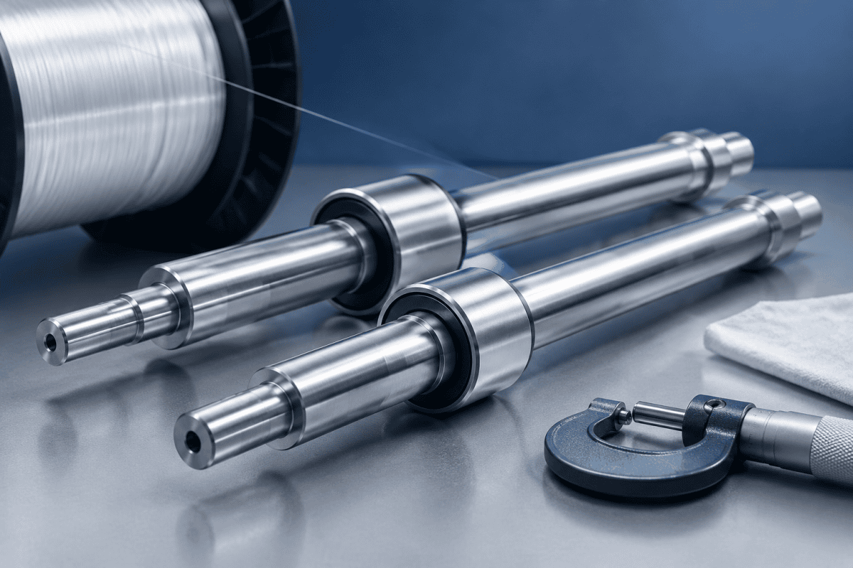
광섬유 가이드 롤러 샤프트는 화염 경로에 위치하거나 증착 온도에서 유리와 접촉하지 않기 때문에 간과하기 쉽습니다. 그러나 실제로 광섬유 가이드 롤러 샤프트는 권선, 인발 및 권취 스테이션 전반에 걸쳐 유리 섬유, 코팅 섬유 또는 프리폼 핸들링 픽스처가 어떻게 지지되고, 정렬되고, 회전되는지를 정의합니다. 샤프트가 공차를 벗어나 작동하거나, 베어링에 제대로 안착되지 않거나, 롤러 본체와 잘 맞물리지 않으면 그 결과는 섬유 흔들림, 불균일한 장력 또는 단일 부품으로 추적하기 어려운 표면 자국으로 나타납니다.
이 글에서는 광섬유 가이드 롤러 샤프트를 지정할 때 중요한 사항, 정밀 가공 방법, 그리고 조립 중 및 교체 후 확인해야 할 사항을 살펴봅니다.
가이드 롤러 샤프트가 실제로 하는 일
광섬유 가이드 롤러 샤프트는 롤러 본체와 기계 프레임 사이의 구조적 및 회전 인터페이스 역할을 합니다. 스테이션에 따라 가이드 롤러 샤프트는 회전하지 않고 고정되어 롤러가 그 주위에 장착된 베어링 위에서 회전하거나, 구동 어셈블리의 일부로 롤러와 함께 회전할 수 있습니다. 섬유 권선 및 권취 위치에서 샤프트는 공정에 필요한 라인 속도에서 원활하고 저진동 회전을 허용하면서 롤러를 안정적인 축방향 위치에 유지해야 합니다.
샤프트는 여러 공차를 함께 결합하기 때문에 작은 편차가 증폭될 수 있습니다. 샤프트 직진도, 저널 직경, 숄더 직각도, 키홈 또는 플랫 위치, 나사 품질 및 표면 조도는 모두 롤러가 어떻게 안착되고 회전하는지에 영향을 미칩니다. 권선 스테이션에서 롤러 면 위치는 섬유가 놓이는 위치에 영향을 미칩니다. 가이드 위치에서 런아웃은 섬유 경로를 편향시키고 롤러의 한쪽에서 다른 쪽으로 장력을 약간 변화시킬 수 있습니다.
이러한 영향은 일반적으로 누적되므로 샤프트 품질은 개별적으로가 아니라 조립 중에 판단됩니다.
또한 샤프트의 역할과 롤러 자체의 역할을 구분하는 것도 도움이 됩니다. 롤러는 접촉 형상, 표면 상태 및 섬유에 대한 마찰을 제어합니다. 샤프트는 위치, 정렬 및 회전 안정성을 제어합니다. 스테이션에 결함이 발생하면 두 가지가 종종 상호 교환적으로 비난받으므로, 유용한 첫 단계는 부품을 제거하기 전에 실제로 어떤 기능이 실패하고 있는지 결정하는 것입니다.
광섬유 가이드 롤러 샤프트의 정밀 가공 고려사항
재료 선택은 응용 분야에 따라 결정된다
광섬유 가이드 롤러 샤프트에 대한 단일 정답 재료는 없습니다. 선택은 하중, 속도, 마모 환경, 부식 노출, 중량 제한 및 샤프트 구동 여부에 따라 달라집니다. 일반적인 옵션으로는 내식성 및 세정성을 위한 스테인리스강, 열처리 시 더 높은 강도와 내마모성을 위한 합금강, 회전 질량 감소가 중요한 경우 알루미늄 합금이 있습니다.
재료 적합성은 광범위한 제품 카테고리에서 가정하기보다는 부품의 실제 기능 및 작동 조건에 대해 확인해야 합니다. 코팅 또는 세정 영역 근처에서 작동하는 샤프트는 건조하고 밀폐된 권선기 내의 샤프트와 다른 내식성이 필요할 수 있습니다. 인접 하드웨어에 알루미늄 부품이 사용되는 경우, 기계의 다른 곳에 사용되는 OVD 알루미늄 부품에도 유사한 논리가 적용되지만, 롤러 샤프트 요구사항은 그 자체의 기준으로 평가해야 합니다.
열처리 및 표면 처리 결정은 모재와 동시에 문서화해야 합니다. 침탄, 질화, 패시베이션 및 코팅은 각각 치수를 약간 변화시키므로, 처리를 나열하지 않은 재료 사양은 작업대에서는 맞지만 설치 후에는 끼이는 부품을 생산할 수 있습니다. 내식성 샤프트의 경우, 패시베이션 및 세정 요구사항은 종종 합금 선택만큼 중요합니다.
롤러 거동을 제어하는 공차
광섬유 가이드 롤러 샤프트에서 가장 영향력 있는 가공 특징은 일반적으로 다음과 같습니다:
- 베어링 저널. 직경 공차와 진원도는 베어링 끼워맞춤과 내부 클리어런스를 결정합니다. 너무 느슨하면 샤프트가 크리프하거나 프레팅될 수 있고, 너무 tight하면 베어링 예압이 상승하여 열과 항력이 증가합니다.
- 직진도. 샤프트 축을 따른 굽힘은 롤러 면에서 런아웃을 발생시켜 측방향 섬유 이동으로 이어집니다.
- 숄더 직각도. 축에 대해 직각이 아닌 숄더는 클램핑 시 롤러 또는 베어링을 약간 축에서 벗어나게 밀어냅니다.
- 저널 간 동심도. 구동측과 롤러측 저널이 동심이 아니면, 각 저널이 개별적으로 크기 내에 있더라도 롤러가 정확하게 회전할 수 없습니다.
- 표면 조도. 저널 조도는 베어링 안착과 마모에 영향을 미칩니다. 밀봉 표면과 섬유 대면 표면은 별도의 조도 요구사항이 있을 수 있습니다.
직경뿐만 아니라 런아웃이 종종 실질적인 한계입니다. 샤프트가 직경에서 올바르게 측정되더라도 총 지시 런아웃이 높으면 눈에 띄는 롤러 흔들림을 유발할 수 있습니다.
조립에 영향을 미치는 특징
Optical Fiber Guide Roller Shafts는 일반적으로 리텐션 기능을 갖추고 있습니다: 숄더, 리테이닝 링 홈, 나사산, 키웨이, 플랫 또는 크로스 드릴드 홀 등입니다. 이들의 위치 공차는 크기만큼이나 중요합니다. 각도 위치가 약간 어긋나게 절삭된 키웨이는 의도된 인덱스에 대해 롤러를 회전시키게 되며, 이는 롤러 타이밍이나 피치가 제어되는 구동 어셈블리에서 중요합니다. Locknuts와 함께 사용되는 나사산은 축에 대해 직각이어야 합니다. 반경 방향으로 편심된 나사산은 너트를 기울게 하고, 결과적으로 내부 베어링 레이스를 기울게 합니다.
작은 기하학적 디테일 또한 비용과 리드 타임에 영향을 미칩니다. 저널 진입부의 챔퍼나 라운드는 설치 중 베어링을 보호하지만, 과도한 리드인은 실효 안착 길이를 감소시킵니다. 나사산 릴리프를 위한 언더컷은 결합 너트가 숄더에 완전히 안착될 수 있도록 치수가 설정되어야 합니다. 도면에 이러한 기능을 명시하면, 그렇지 않으면 정확한 샤프트가 납품 후 재작업이 필요하게 되는 상황을 방지할 수 있습니다.
라인 가동 전 조립 검사
올바른 조립 관행은 대부분의 샤프트 관련 문제를 생산 단계에 도달하기 전에 발견할 수 있습니다. 아래 점검 사항은 일반적인 것이며, 특정 스테이션 및 장비 문서에 맞게 조정되어야 합니다.
청결도와 끼워맞춤을 먼저 확인하라
저널과 결합 보어의 버, 흠집, 가공 잔류물을 검사하십시오. 저널의 버는 설치 중 베어링을 긁을 수 있으며, 버가 무너진 후 변화하는 거짓 끼워맞춤을 만들 수 있습니다. 가능한 경우 중요한 인터페이스를 드라이 피팅하여 구성품이 힘만으로가 아니라 손 또는 제어된 프레스 힘으로 안착되는지 확인하십시오.
조립 후에 런아웃을 측정하라, 조립 전만이 아니라
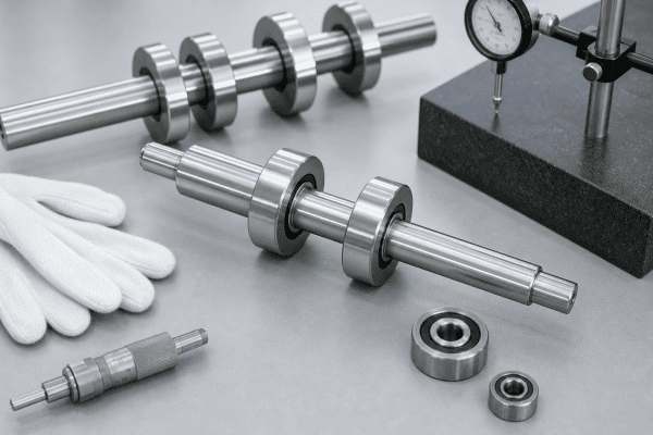
벤치에서 정확하게 회전하는 샤프트도 롤러, 베어링 및 리테이닝 하드웨어가 설치되면 런아웃이 나타날 수 있습니다. 어셈블리를 지지대 또는 적절한 검사 픽스처에 장착하고 롤러 면과 샤프트 연장부를 인디케이트하십시오. 조립 후에만 런아웃이 나타나는 경우, 원인은 종종 샤프트 자체가 아니라 안착, 오염 또는 직각이 아닌 숄더입니다. 이러한 가능성을 구분하는 것이 올바른 진단과 불필요한 교체의 차이입니다.
축방향 위치와 엔드 플로트를 확인하라
롤러가 의도된 축 방향 위치에 있는지, 베어링이 지정된 엔드 플로트 또는 예압을 가지고 있는지 확인하십시오. 과도한 엔드 플로트는 파이버 장력 하에서 롤러가 이동하게 합니다. 불충분한 클리어런스는 바인딩과 열을 유발할 수 있습니다. 리테이닝 링, 스페이서 및 locknuts는 완전히 안착되고 지정된 방법으로 조여져야 하며, 모든 잠금 기능이 체결되어야 합니다.
회전 품질을 확인하라
Rotate the assembly by hand and then at low speed where safe to do so. Look for smooth rotation, absence of rough spots, and no audible or felt catching. Roughness can come from a damaged bearing, a contaminated journal, or a shaft that is slightly bent. If the roller has a driven input, check that the coupling or drive feature engages without forcing the shaft off-axis.
For related take-up and cutting hardware, the same assembly discipline applies to the optical fiber winder clamp and cutter assembly, where alignment and seating affect cut quality and bobbin changeover.
일반적인 증상과 그들이 시사하는 바
When a winding or guide station misbehaves, optical fiber guide roller shafts are one of several possible causes. The table below frames symptoms as possibilities to investigate, not confirmed diagnoses. Verification steps are included because guessing at the cause usually leads to replacing the wrong part.
- Fiber wanders laterally across the roller. Possible causes include shaft runout, a bent shaft, worn bearings, or incorrect roller axial position. Verify by indicating the roller face and checking bearing condition and spacer stack-up.
- Uneven tension from side to side. Possible causes include roller misalignment, a tapered or worn roller surface, or a shaft that is not parallel to the fiber path. Verify alignment against the equipment datum and inspect the roller surface.
- Vibration that increases with speed. Possible causes include imbalance, bearing damage, or shaft straightness error. Verify with a low-speed run and, where available, vibration measurement before disassembly.
- Bearing overheating or short life. Possible causes include incorrect journal fit, excessive preload, insufficient clearance, or lubrication issues. Verify journal dimensions and the specified fit before replacing bearings.
- Surface marks on fiber. Possible causes include a damaged roller surface, contamination, or a guide misalignment that increases contact pressure. Verify the fiber path and inspect all contact surfaces, not only the shaft.
Recording the measurements taken at each step makes it easier to decide whether the shaft needs replacement, the assembly needs re-shimming, or another component is at fault. A simple log that tracks runout, end float, and bearing temperature over time is often more useful than a single measurement taken after a failure.
라인에 투입되는 체크리스트
A compact checklist keeps the sequence consistent between shifts and between technicians. The order matters, because checking rotation quality before verifying fit can hide a seating problem behind a temporarily smooth feel.
- Confirm the correct part number and revision against the equipment documentation.
- Inspect journals, shoulders, threads, and retention features for damage.
- Clean all mating surfaces and verify that bores and bearings are free of debris.
- Dry-fit the assembly and confirm seating by hand or with controlled press force.
- Indicate the shaft extension and roller face after assembly, not before.
- Confirm axial position, end float, and locking hardware engagement.
- Rotate by hand, then at low speed, and note any roughness or sound.
- Record the measured values so the next check has a baseline to compare against.
재설치가 아닌 교체가 필요한 시점
Replacement is usually justified when a journal is worn below its specified range, when straightness cannot be restored, when retention features are damaged, or when corrosion or galling has degraded a critical surface. Reusing a marginal shaft often transfers the problem to new bearings, which then fail early and obscure the original cause.
Before ordering, gather the information a supplier needs: a drawing or sketch with dimensions, the material and any heat treatment, critical tolerances and surface finish requirements, the quantity, and the operating conditions the shaft sees. For non-standard or obsolete optical fiber guide roller shafts, drawing-based production and reverse engineering may be the practical route, which is where OEM/ODM CNC machining services can produce components to matched dimensions rather than forcing a redesign around an off-the-shelf part.
It is also worth checking whether the failure is recurring. A shaft that fails repeatedly at the same station may point to an alignment problem, a drive issue, or an overload condition that a new part alone will not correct. In those cases, measuring the installed geometry before ordering a replacement saves a second failure.
맞춤형 가이드 롤러 샤프트 지정
Custom guide roller shafts are typically specified when the original dimensions must be matched, when a station has been modified, or when material and finish need to change for a specific environment. A clear specification should state:
- Overall geometry and all functional dimensions, with datums identified
- Material grade and condition, plus any required treatment
- Critical tolerances, runout limits, and surface finish
- Retention features and their position tolerances
- Quantity and whether prototype and production quantities are both expected
If only a worn sample is available, a measured drawing plus notes on the original function helps the supplier interpret which features are critical and which have latitude. For broader replacement needs across a line, reviewing optical fiber winder shafts and sleeves can help identify which components are standard versus made to order, and the same drawing-based approach applies to related hardware such as optical fiber winding spool hubs where bore and shaft interface tolerances matter.
왕복 커뮤니케이션을 줄여주는 도면 세부사항
Suppliers can usually quote faster when the drawing answers a few questions up front. Datum selection should reflect how the part is measured and installed, not just how it is machined. Critical dimensions should be marked rather than leaving every dimension at the same tolerance, since a fully tight drawing raises cost without improving function.
Inspection expectations should also be stated. If optical fiber guide roller shafts will be verified for runout or journal diameter on receipt, the drawing should define how that measurement is taken so supplier and buyer agree on the result. Where a first article inspection is required, noting it in the request avoids a dispute after delivery.
프로토타입 및 생산 수량
Many replacement shafts begin as a single prototype to confirm fit before a larger batch is ordered. Machining setup, tooling, and inspection effort are spread differently across a single unit and a production run, so it helps to state both quantities in the original inquiry. This lets the supplier plan processes that will hold tolerance consistently as volume increases.
검사 및 문서화 관행
Inspection records turn a one-time replacement into a repeatable process. When the measured values for journals, runout, and shoulder squareness are documented, the next order can reference actual data instead of a worn sample. This is particularly useful for equipment that is no longer supported by the original builder.
Where possible, measurements should be taken with instruments suited to the tolerance being checked. A caliper is adequate for overall lengths and non-critical diameters, but journal diameter and roundness are better verified with a micrometer and a method that detects lobing. Runout needs a dial indicator and a stable reference, and the reference itself must be clean and undamaged or the reading is meaningless.
자주 묻는 질문
광섬유 가이드 롤러 샤프트를 교체하지 않고 교정할 수 있습니까?
Straightening is possible in some cases, but it can introduce residual stress and may not restore journal condition or surface finish. It is generally considered only when the shaft is otherwise sound and the required straightness is modest. Replacing the shaft is more predictable when journals or retention features are also worn.
런아웃이 샤프트에서 오는지 롤러에서 오는지 어떻게 알 수 있습니까?
Indicate the shaft extension and the roller face separately after assembly. If the shaft extension runs true but the roller face does not, the issue is likely in the roller bore, bearing seating, or spacer stack. If both show runout, inspect the shaft and its support.
샤프트 재료가 광섬유 품질에 직접 영향을 미칩니까?
Not through contact with the fiber in most stations, but material affects stiffness, mass, corrosion resistance, and dimensional stability. A shaft that bends or corrodes can change alignment over time, which then affects fiber handling indirectly. Material should be selected for the mechanical and environmental demands of the station.
맞춤형 광섬유 가이드 롤러 샤프트 요청 시 무엇을 포함해야 합니까?
Provide a drawing or measured sketch, material and treatment requirements, critical tolerances and runout limits, surface finish, quantity, and a description of the operating conditions. Photos of the installed assembly and notes on the failure mode also help the supplier assess which features matter most.
가이드 롤러 샤프트는 얼마나 자주 검사해야 합니까?
Inspection intervals depend on line speed, load, and environment, but a practical approach is to check runout and bearing condition at planned maintenance intervals and after any event that could have overloaded the station. Trending the readings is more valuable than a single pass or fail result.
광섬유 가이드 롤러 샤프트를 전체 도면 없이 공급할 수 있습니까?
A complete drawing is preferred, but a measured sample with notes on critical features is often enough to begin. The supplier will normally confirm which dimensions are functional and which can vary before production starts.
다음 단계
If a winding or guide station is showing runout, tension variation, or premature bearing wear, the fastest path to a reliable fix is a clear specification for optical fiber guide roller shafts. Send your drawings, dimensions, material requirements, and operating conditions to request a quotation and confirm whether a standard replacement or a custom-machined shaft best fits the application.
For additional guidance on precision measurement and tolerance practices, consult the ISO 2768 general tolerances standard, which many suppliers reference when defining default tolerance classes on machined drawings.
