
Connaissances
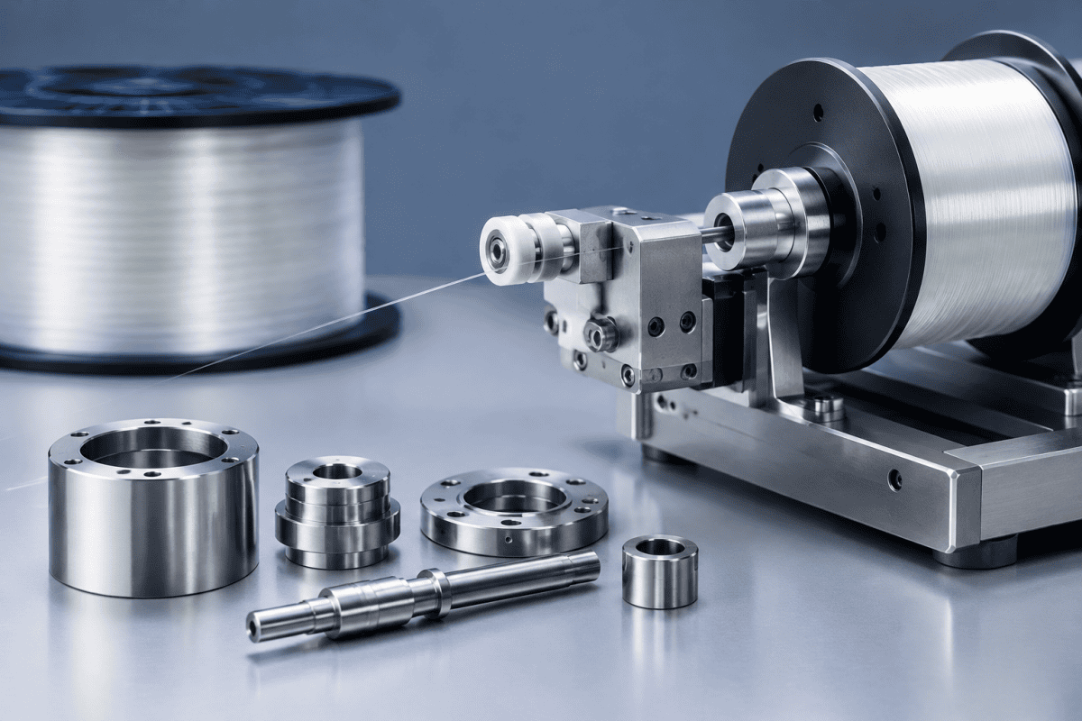
Pièces d'équipement de test de résistance de fibre optique : Composants de rembobinage usinés sur mesure
FAQ
Optical Fiber Proof Test Equipment Parts sit at the point where a finished fiber is validated and repackaged, so any mechanical problem there affects the whole production schedule. Fiber is pulled under controlled tension through capstans, sheaves, guide rollers, and dancer assemblies, and a single worn or misaligned component can cause slips, surface damage, or false proof-test alarms. Sourcing reliable optical fiber proof test equipment parts is therefore less about finding the cheapest replacement and more about matching each component to its load path, wear mode, and alignment requirements.
How Proof-Test and Rewind Lines Differ From Draw or Deposition Equipment
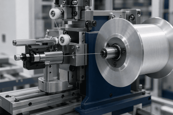
Proof-test equipment applies a controlled tensile load to verify that fiber meets a minimum strength specification, while rewind machines move fiber from one spool to another at controlled tension and speed. Both processes are mechanical rather than thermal, and neither uses the high-temperature burners or deposition torches found in OVD, VAD, or MCVD preform manufacturing. The distinction matters because a component that performs well in a hot deposition environment is not automatically the right choice for a room-temperature tension and guide system.
Compared with OVD or VAD equipment, proof-test and rewind hardware tends to be dominated by:
- Rotating contact parts — capstans, sheaves, guide rollers, and pulley assemblies
- Tension-control elements — dancer arms, load-cell mounting fixtures, and brake or clutch interface parts
- Fibre-handling surfaces — guide grooves, ceramic or coated contact faces, and entry/exit bushings
- Spool and bobbin interfaces — chucks, adapters, clamping collars, and take-up mandrels
- Cutter and clamp mechanism parts used during bobbin changeover
Because these parts interact directly with bare or coated fiber, surface finish, concentricity, and groove geometry often matter more than raw strength. A roller that runs true but has a rough contact surface can still damage fiber, and a perfectly smooth roller mounted off-axis can introduce tension variation that shows up as noise in proof-test data.
Maintenance teams that also support preform manufacturing should keep the two worlds separate. The wear mechanisms, cleanliness requirements, and even the fasteners differ enough that cross-applying parts between optical fiber proof test equipment parts and deposition hardware usually creates more problems than it solves.
Common Failure Points and How to Investigate Them
When a proof-test or rewind line starts producing inconsistent results, the cause is often mechanical rather than electrical. The following sections separate likely causes from confirmed diagnoses, since replacing a part before confirming the root cause can simply move the problem to the next component.
1. Tension instability and false proof-test readings
Possible causes: worn guide roller bearings, damaged dancer pivot, contamination on a capstan surface, or a load-cell mount that has shifted.
How to verify: Isolate the tension zone by running a known-good fiber through the line and comparing measured tension at each sensor. If tension varies with roller rotation but not with fiber grade, the roller is the likely source. Inspect bearings for roughness or axial play, and check that roller grooves are free of embedded debris. A load-cell reading that drifts without a corresponding mechanical change should be checked against the mount and cable routing before the cell itself is replaced.
Because this zone does most of the work in the machine, small alignment errors here are the most common root cause behind rejected optical fiber proof test equipment parts during planned overhauls. A dial indicator reading taken at the roller face will often reveal a problem that looks electrical on the HMI.
2. Fiber surface damage or coating marks
Possible causes: a scored or chipped guide surface, a misaligned entry bushing, or a roller groove that no longer matches the fiber diameter.
How to verify: Run a short length of fiber through the suspect path and inspect it under magnification at each contact point. Damage that appears at a consistent position along the fiber length points to a specific roller or bushing. Confirm the groove profile against the drawing rather than assuming a visually similar part is interchangeable.
3. Spool or bobbin slippage during rewind
Possible causes: worn chuck jaws, a deformed clamping collar, or an adapter that no longer matches the bobbin hub.
How to verify: Mark the bobbin and chuck, run a short rewind cycle, and check for relative movement. If slippage is confirmed, measure the chuck and hub dimensions against the original drawing before ordering a replacement. In many cases the fix is a new adapter or collar rather than a full chuck assembly.
4. Cutter or clamp faults at changeover
Possible causes: dulled blade, worn pivot, or a clamp that no longer holds consistent force.
How to verify: Inspect the blade edge and pivot for wear, and check clamp force against the equipment documentation. Cutter and clamp assemblies are often treated as consumables, so it is worth confirming whether the whole assembly or just the blade needs replacement.
For lines that also handle take-up and bobbin changeover, components such as the optical fiber winder cutter assembly parts are often replaced as a matched set because the clamp and cutter wear together.
Material and Design Choices for Rewind Mechanical Parts
Fiber rewind machine components rarely fail for lack of strength. They fail because a material choice did not match the contact conditions. When evaluating a replacement or specifying a new part, consider:
- Contact material: Surfaces that touch fiber should be chosen for smoothness, wear resistance, and compatibility with the coating. Metals that can shed particles or develop sharp edges are poor choices for direct fiber contact.
- Coating or surface treatment: Coatings can improve wear life, but they must be applied consistently. An uneven coating can create a high spot that damages fiber.
- Bearing selection: Bearing type affects runout, drag, and service interval. High-speed rewind lines may need different bearings than low-speed proof-test stations.
- Alignment features: Pilot diameters, locating shoulders, and keyways are what keep a roller or capstan running true. These features should be inspected and specified on the drawing, not assumed.
- Balance and concentricity: For rotating parts, imbalance shows up as vibration, which in turn shows up as tension noise. Concentricity tolerances should reflect the operating speed of the line.
- Cleaning and changeover: Parts that are easy to remove and clean reduce the risk of contamination being pushed into a fiber path.
Aluminum is frequently used for structural brackets and non-contact housings, but it is generally a poor choice for direct fiber contact surfaces unless a suitable surface treatment is applied. Where aluminum components are relevant to a rewind or handling assembly, they should be evaluated on function and surface condition rather than assumed suitable. The same principle applies across aluminum VAD burner hardware and other precision components: material suitability depends on the specific contact, load, and environment.
Contamination control is another design variable that is easy to overlook. A part that traps fiber dust or coating debris will eventually transfer that material back onto the fiber path, creating defects that appear intermittent and are difficult to trace. Whenever possible, specify radii, relief grooves, and drainage features that let debris fall away instead of collecting near a contact surface. That approach is standard practice in precision fiber handling, and it is the same logic behind our guide to arbres de rouleau de guidage de fibre optique and their assembly checks.
Balancing cost, lead time, and wear life
Purchasing teams often face pressure to reduce the unit cost of optical fiber proof test equipment parts, but the cheapest option rarely wins over a full maintenance cycle. A low-cost roller that wears twice as fast may require two replacements and two line stoppages in the time a properly specified part lasts. When comparing quotes, it helps to evaluate cost per operating hour rather than cost per piece, and to ask suppliers how the material and tolerances were selected for the application.
Lead time matters just as much as price on a line that cannot run without a specific component. Keeping one or two wear-critical spares on the shelf is usually cheaper than an expedited custom run, and it gives maintenance time to inspect the failed part properly instead of reinstalling a marginal one.
What to Include in a Replacement Sourcing Request
Rewind and proof-test parts are often non-standard, so a clear sourcing request saves time on both sides. A useful request typically includes:
- Drawings or sketches with critical dimensions, tolerances, and surface finish requirements
- Material and surface treatment requirements, or a description of the operating conditions if no material is specified
- Quantity and application — prototype, spare, or production replacement
- Interface details — shaft diameter, mounting pattern, gas or fluid connections if applicable, and any keyway or locating features
- Operating conditions — speed, tension range, fiber type, and ambient environment
- Reference part number or photo of the existing component, where available
When an original drawing is not available, reverse engineering from a physical sample is often feasible. This usually involves measuring critical dimensions, identifying material and any surface treatment, and confirming fit with the mating parts before production. For non-standard or obsolete rewind components, custom machining services can produce parts from drawings or samples, provided the dimensions and application requirements are clearly defined.
It is also worth checking whether the component is part of a broader assembly. A guide roller that appears to be a standalone part may actually be one element of a tension-control module, and replacing only part of the module can leave a wear mismatch. Where a range of replacement options is needed, browsing the overall optical fiber equipment parts range can help confirm whether a standard item exists before committing to a custom run.
Specification details that are commonly forgotten include plating thickness, allowable runout after assembly, and the matching surface finish of the mating bore. Adding these to the request avoids a situation where a part arrives within its own drawing tolerance but still does not assemble correctly with the rest of the line. If tolerances on optical fiber proof test equipment parts are not clearly stated, suppliers may default to general machining tolerances that are too loose for a fiber contact application.
Maintenance Practices That Extend Rewind Component Life
Rewind and proof-test parts are mechanical rather than thermal, so maintenance practices differ from burner and torch care. Practical measures include:
- Recording runout and tension readings at each scheduled service so trends are visible before a failure occurs
- Inspecting fiber contact surfaces for scoring, embedded debris, or coating buildup
- Checking roller and capstan bearings for play, noise, or temperature rise
- Verifying that replacement parts match the original drawing before installation
- Keeping spares for the highest-wear items so a fault does not stop the line
Where the same fiber path handles multiple fiber types or diameters, it is worth reviewing whether the guide and roller geometry still suits the current product mix. A line that has changed fiber specifications may be running with components sized for a different range, which can cause tension variation even when the parts themselves are in good condition.
For readers who want to understand how mechanical parts degrade across different fiber processes, the Telecommunications Industry Association publishes the fiber optic test procedures that define many proof-test and measurement methods. Comparing the equipment requirements in that standard with the condition of the line’s mechanical hardware is a practical way to spot a drifting process before it produces out-of-spec fiber.
Service records are most useful when they are tied to specific part numbers and positions on the line. Recording which roller, bushing, or chuck was replaced, and at what running hours, makes it possible to compare wear rates between suppliers and to justify a change in material or coating when the data supports it.
Verifying Fit and Quality After Delivery
Receiving inspection is the last chance to catch a problem before it reaches the line. For optical fiber proof test equipment parts, a light but consistent inspection routine pays for itself quickly.
- Confirm the part number, revision, and quantity against the purchase order and drawing
- Check critical diameters, groove profiles, and locating features with calibrated instruments
- Inspect contact surfaces for tool marks, burrs, coating defects, or embedded debris
- Verify that any keyway, shoulder, or pilot diameter seats correctly on the mating part
- Rotate assembled rollers and capstans to confirm smooth running with no detectable play
Where a batch of replacement parts is being introduced for the first time, it is worth running a short qualification trial on the line and comparing tension readings against the previous baseline. This catches subtle differences in balance or surface finish that are hard to see by eye but show up clearly in measurement data.
FAQ
Can proof-test and rewind parts be used interchangeably with OVD torch or burner parts?
No. Proof-test and rewind components operate at room temperature under mechanical tension and contact loads, while OVD and VAD burners operate under high-temperature deposition conditions. The materials, tolerances, and surface requirements are different, and parts should be specified for their actual application.
How do I know whether a rewind roller needs replacement or just adjustment?
Measure runout and inspect the contact surface. If runout is within the equipment specification and the surface is undamaged, adjustment or cleaning may be sufficient. If runout exceeds the specification or the surface shows scoring or embedded debris, replacement is usually the more reliable option.
What information is needed to quote a custom rewind component?
A drawing or sample, material and surface treatment requirements, critical dimensions and tolerances, quantity, and a description of the operating conditions. If a drawing is unavailable, a physical sample and the mating dimensions are usually enough to begin.
Are aluminum parts suitable for fiber contact surfaces?
Aluminum is often used for structural and non-contact components where weight and machinability matter. For direct fiber contact, the surface condition and any applied treatment are the deciding factors, so the material should be selected based on the actual contact and wear requirements rather than on the metal alone.
How should optical fiber proof test equipment parts be stored before installation?
Keep them in original packaging or clean protective covers until the line is ready, away from dust, moisture, and metalworking areas. Contact surfaces should be inspected again immediately before installation, since a part that sat open on a bench can pick up debris that is difficult to see.
How often should optical fiber proof test equipment parts be replaced?
There is no universal interval, because it depends on line speed, tension, fiber coating, and hours per week. The practical approach is to trend runout and tension readings at each service and replace an optical fiber proof test equipment parts item when the trend shows drift, rather than waiting for a failure or following a fixed calendar schedule.
Prochaine étape
If a proof-test or rewind component is causing tension variation, fiber damage, or repeat changeover faults, the fastest route to a reliable replacement is to share the drawing, dimensions, material requirements, and operating conditions with the supplier. You can discuss your component requirements directly, including reverse-engineering from a sample where no drawing exists, and confirm fit against the mating parts before production begins.
Reliable optical fiber proof test equipment parts come from clear specifications and confirmed fits, not from guesswork. Whether the need is a single replacement roller or a batch of custom rewind mechanical parts, matching the component to its actual load path and contact conditions is what keeps a proof-test or rewind line running at spec.
