
Wissen
Teile für Optische-Faser-Nachweisprüfanlagen: Kundenspezifisch bearbeitete Aufwickelkomponenten
Okt.
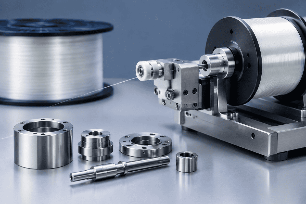
Teile für optische Faser-Proof-Test-Geräte befinden sich an dem Punkt, an dem eine fertige Faser validiert und neu verpackt wird, sodass jedes mechanische Problem dort den gesamten Produktionsplan beeinflusst. Die Faser wird unter kontrollierter Spannung durch Capstans, Sheaves, Führungswalzen und Tänzerbaugruppen gezogen, und eine einzige abgenutzte oder fehlausgerichtete Komponente kann zu Rutschen, Oberflächenschäden oder falschen Proof-Test-Alarmen führen. Die Beschaffung zuverlässiger Teile für optische Faser-Proof-Test-Geräte ist daher weniger eine Frage der Suche nach dem günstigsten Ersatz, sondern vielmehr der Abstimmung jeder Komponente auf ihren Lastpfad, ihr Verschleißverhalten und ihre Ausrichtungsanforderungen.
Wie sich Proof-Test- und Rewind-Linien von Draw- oder Deposition-Anlagen unterscheiden
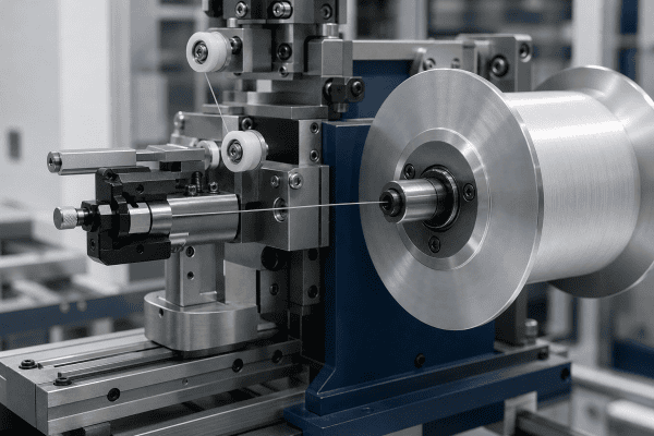
Proof-Test-Geräte üben eine kontrollierte Zuglast aus, um zu überprüfen, ob die Faser eine Mindestfestigkeitsspezifikation erfüllt, während Rewind-Maschinen die Faser mit kontrollierter Spannung und Geschwindigkeit von einer Spule auf eine andere bewegen. Beide Prozesse sind mechanisch und nicht thermisch, und keiner verwendet die Hochtemperaturbrenner oder Abscheidungsbrenner, die in der OVD-, VAD- oder MCVD-Preform-Herstellung zu finden sind. Die Unterscheidung ist wichtig, weil eine Komponente, die in einer heißen Abscheidungsumgebung gut funktioniert, nicht automatisch die richtige Wahl für ein Raumtemperatur-Spannungs- und Führungssystem ist.
Im Vergleich zu OVD- oder VAD-Anlagen wird die Proof-Test- und Rewind-Hardware tendenziell dominiert von:
- Rotierenden Kontaktteilen — Capstans, Sheaves, Führungswalzen und Riemenscheibenbaugruppen
- Spannungssteuerungselementen — Tänzerarme, Wägezellen-Montagevorrichtungen und Brems- oder Kupplungsschnittstellenteile
- Faserhandhabungsoberflächen — Führungsnuten, keramische oder beschichtete Kontaktflächen und Ein-/Ausgangsbuchsen
- Spulen- und Bobbin-Schnittstellen — Spannfutter, Adapter, Klemmringe und Aufwickeldorne
- Messer- und Klemmmechanismusteile, die beim Bobbin-Wechsel verwendet werden
Da diese Teile direkt mit blanker oder beschichteter Faser interagieren, sind Oberflächenbeschaffenheit, Rundlauf und Nutgeometrie oft wichtiger als die reine Festigkeit. Eine Walze, die rund läuft, aber eine raue Kontaktfläche hat, kann die Faser dennoch beschädigen, und eine perfekt glatte Walze, die außeraxial montiert ist, kann Spannungsschwankungen einführen, die als Rauschen in den Proof-Test-Daten sichtbar werden.
Wartungsteams, die auch die Preform-Herstellung unterstützen, sollten die beiden Welten getrennt halten. Die Verschleißmechanismen, Sauberkeitsanforderungen und sogar die Befestigungselemente unterscheiden sich so stark, dass die Kreuzanwendung von Teilen zwischen optischen Faser-Proof-Test-Geräteteilen und Abscheidungshardware normalerweise mehr Probleme schafft als löst.
Häufige Ausfallpunkte und wie man sie untersucht
Wenn eine Proof-Test- oder Rewind-Linie beginnt, inkonsistente Ergebnisse zu liefern, ist die Ursache oft mechanisch und nicht elektrisch. Die folgenden Abschnitte trennen wahrscheinliche Ursachen von bestätigten Diagnosen, da das Ersetzen eines Teils vor der Bestätigung der Grundursache das Problem einfach auf die nächste Komponente verschieben kann.
Spannungsinstabilität und falsche Proof-Test-Messwerte
Mögliche Ursachen: abgenutzte Führungswalzenlager, beschädigter Tänzerdrehpunkt, Verunreinigung auf einer Capstan-Oberfläche oder eine verschobene Wägezellenhalterung.
Verifizierung: Isolieren Sie die Spannungszone, indem Sie eine bekanntermaßen gute Faser durch die Linie führen und die gemessene Spannung an jedem Sensor vergleichen. Wenn die Spannung mit der Walzendrehung, aber nicht mit der Fasersorte variiert, ist die Walze die wahrscheinliche Quelle. Überprüfen Sie die Lager auf Rauheit oder axiales Spiel und stellen Sie sicher, dass die Walzennuten frei von eingebetteten Rückständen sind. Ein Wägezellenmesswert, der ohne entsprechende mechanische Änderung driftet, sollte gegen die Halterung und Kabelverlegung überprüft werden, bevor die Zelle selbst ersetzt wird.
Da diese Zone die meiste Arbeit in der Maschine leistet, sind kleine Ausrichtungsfehler hier die häufigste Grundursache für zurückgewiesene Teile für optische Faser-Proof-Test-Geräte während geplanter Überholungen. Ein Messuhr-Messwert an der Walzenstirnfläche zeigt oft ein Problem auf, das auf dem HMI elektrisch erscheint.
Faseroberflächenschäden oder Beschichtungsmarkierungen
Mögliche Ursachen: eine verkratzte oder abgeplatzte Führungsfläche, eine fehlausgerichtete Eingangsbuchse oder eine Walzennut, die nicht mehr zum Faserdurchmesser passt.
Verifizierung: Führen Sie ein kurzes Stück Faser durch den verdächtigen Pfad und untersuchen Sie es unter Vergrößerung an jedem Kontaktpunkt. Schäden, die an einer konsistenten Position entlang der Faserlänge auftreten, deuten auf eine bestimmte Walze oder Buchse hin. Bestätigen Sie das Nutprofil anhand der Zeichnung, anstatt anzunehmen, dass ein visuell ähnliches Teil austauschbar ist.
Spulen- oder Bobbin-Rutschen während des Rewind
Mögliche Ursachen: abgenutzte Spannfutterbacken, ein verformter Klemmring oder ein Adapter, der nicht mehr zur Bobbin-Nabe passt.
Verifizierung: Markieren Sie den Bobbin und das Spannfutter, führen Sie einen kurzen Rewind-Zyklus durch und prüfen Sie auf relative Bewegung. Wenn ein Rutschen bestätigt wird, messen Sie die Spannfutter- und Nabenabmessungen gegen die Originalzeichnung, bevor Sie einen Ersatz bestellen. In vielen Fällen ist die Lösung ein neuer Adapter oder Ring anstelle einer vollständigen Spannfutterbaugruppe.
Messer- oder Klemmenfehler beim Wechsel
Mögliche Ursachen: stumpfe Klinge, abgenutzter Drehpunkt oder eine Klemme, die keine konsistente Kraft mehr hält.
Verifizierung: Überprüfen Sie die Klingenkante und den Drehpunkt auf Verschleiß und prüfen Sie die Klemmkraft gegen die Gerätedokumentation. Messer- und Klemmenbaugruppen werden oft als Verbrauchsmaterialien behandelt, daher lohnt es sich zu bestätigen, ob die gesamte Baugruppe oder nur die Klinge ersetzt werden muss.
Für Linien, die auch Aufwicklung und Bobbin-Wechsel handhaben, werden Komponenten wie die Teile der Messerbaugruppe für optische Faser-Wickler oft als abgestimmtes Set ersetzt, da Klemme und Messer zusammen verschleißen.
Material- und Designauswahl für mechanische Rewind-Teile
Komponenten von Faserumspulmaschinen versagen selten aufgrund mangelnder Festigkeit. Sie versagen, weil die Materialauswahl nicht mit den Kontaktbedingungen übereinstimmte. Bei der Bewertung eines Ersatzteils oder der Spezifizierung eines Neuteils sind folgende Punkte zu berücksichtigen:
- Kontaktmaterial: Oberflächen, die mit der Faser in Berührung kommen, sollten hinsichtlich Glattheit, Verschleißfestigkeit und Kompatibilität mit der Beschichtung ausgewählt werden. Metalle, die Partikel absondern oder scharfe Kanten entwickeln können, sind keine gute Wahl für den direkten Faserkontakt.
- Beschichtung oder Oberflächenbehandlung: Beschichtungen können die Verschleißlebensdauer verbessern, müssen jedoch gleichmäßig aufgetragen werden. Eine ungleichmäßige Beschichtung kann eine Erhebung erzeugen, die die Faser beschädigt.
- Lagerauswahl: Der Lagertyp beeinflusst Rundlauf, Widerstand und Wartungsintervall. Hochgeschwindigkeits-Umspullinien benötigen möglicherweise andere Lager als langsame Proof-Test-Stationen.
- Ausrichtungsmerkmale: Passdurchmesser, Positionieranschläge und Passfedernuten sind dafür verantwortlich, dass eine Rolle oder ein Capstan rund läuft. Diese Merkmale sollten geprüft und in der Zeichnung spezifiziert werden, nicht vorausgesetzt.
- Balance and concentricity: For rotating parts, imbalance shows up as vibration, which in turn shows up as tension noise. Concentricity tolerances should reflect the operating speed of the line.
- Cleaning and changeover: Parts that are easy to remove and clean reduce the risk of contamination being pushed into a fiber path.
Aluminum is frequently used for structural brackets and non-contact housings, but it is generally a poor choice for direct fiber contact surfaces unless a suitable surface treatment is applied. Where aluminum components are relevant to a rewind or handling assembly, they should be evaluated on function and surface condition rather than assumed suitable. The same principle applies across aluminum VAD burner hardware and other precision components: material suitability depends on the specific contact, load, and environment.
Contamination control is another design variable that is easy to overlook. A part that traps fiber dust or coating debris will eventually transfer that material back onto the fiber path, creating defects that appear intermittent and are difficult to trace. Whenever possible, specify radii, relief grooves, and drainage features that let debris fall away instead of collecting near a contact surface. That approach is standard practice in precision fiber handling, and it is the same logic behind our guide to Lichtwellenleiter-Führungsrollenwellen and their assembly checks.
Abwägung von Kosten, Lieferzeit und Verschleißlebensdauer
Purchasing teams often face pressure to reduce the unit cost of optical fiber proof test equipment parts, but the cheapest option rarely wins over a full maintenance cycle. A low-cost roller that wears twice as fast may require two replacements and two line stoppages in the time a properly specified part lasts. When comparing quotes, it helps to evaluate cost per operating hour rather than cost per piece, and to ask suppliers how the material and tolerances were selected for the application.
Lead time matters just as much as price on a line that cannot run without a specific component. Keeping one or two wear-critical spares on the shelf is usually cheaper than an expedited custom run, and it gives maintenance time to inspect the failed part properly instead of reinstalling a marginal one.
Was in eine Ersatzteil-Beschaffungsanfrage gehört
Rewind and proof-test parts are often non-standard, so a clear sourcing request saves time on both sides. A useful request typically includes:
- Drawings or sketches with critical dimensions, tolerances, and surface finish requirements
- Material and surface treatment requirements, or a description of the operating conditions if no material is specified
- Quantity and application — prototype, spare, or production replacement
- Interface details — shaft diameter, mounting pattern, gas or fluid connections if applicable, and any keyway or locating features
- Operating conditions — speed, tension range, fiber type, and ambient environment
- Reference part number or photo of the existing component, where available
When an original drawing is not available, reverse engineering from a physical sample is often feasible. This usually involves measuring critical dimensions, identifying material and any surface treatment, and confirming fit with the mating parts before production. For non-standard or obsolete rewind components, custom machining services can produce parts from drawings or samples, provided the dimensions and application requirements are clearly defined.
It is also worth checking whether the component is part of a broader assembly. A guide roller that appears to be a standalone part may actually be one element of a tension-control module, and replacing only part of the module can leave a wear mismatch. Where a range of replacement options is needed, browsing the overall optical fiber equipment parts range can help confirm whether a standard item exists before committing to a custom run.
Specification details that are commonly forgotten include plating thickness, allowable runout after assembly, and the matching surface finish of the mating bore. Adding these to the request avoids a situation where a part arrives within its own drawing tolerance but still does not assemble correctly with the rest of the line. If tolerances on optical fiber proof test equipment parts are not clearly stated, suppliers may default to general machining tolerances that are too loose for a fiber contact application.
Wartungspraktiken zur Verlängerung der Lebensdauer von Rewind-Komponenten
Rewind and proof-test parts are mechanical rather than thermal, so maintenance practices differ from burner and torch care. Practical measures include:
- Recording runout and tension readings at each scheduled service so trends are visible before a failure occurs
- Inspecting fiber contact surfaces for scoring, embedded debris, or coating buildup
- Checking roller and capstan bearings for play, noise, or temperature rise
- Verifying that replacement parts match the original drawing before installation
- Keeping spares for the highest-wear items so a fault does not stop the line
Where the same fiber path handles multiple fiber types or diameters, it is worth reviewing whether the guide and roller geometry still suits the current product mix. A line that has changed fiber specifications may be running with components sized for a different range, which can cause tension variation even when the parts themselves are in good condition.
For readers who want to understand how mechanical parts degrade across different fiber processes, the Telecommunications Industry Association publishes the fiber optic test procedures that define many proof-test and measurement methods. Comparing the equipment requirements in that standard with the condition of the line’s mechanical hardware is a practical way to spot a drifting process before it produces out-of-spec fiber.
Service records are most useful when they are tied to specific part numbers and positions on the line. Recording which roller, bushing, or chuck was replaced, and at what running hours, makes it possible to compare wear rates between suppliers and to justify a change in material or coating when the data supports it.
Überprüfung von Passung und Qualität nach der Lieferung
Receiving inspection is the last chance to catch a problem before it reaches the line. For optical fiber proof test equipment parts, a light but consistent inspection routine pays for itself quickly.
- Confirm the part number, revision, and quantity against the purchase order and drawing
- Check critical diameters, groove profiles, and locating features with calibrated instruments
- Inspect contact surfaces for tool marks, burrs, coating defects, or embedded debris
- Verify that any keyway, shoulder, or pilot diameter seats correctly on the mating part
- Rotate assembled rollers and capstans to confirm smooth running with no detectable play
Where a batch of replacement parts is being introduced for the first time, it is worth running a short qualification trial on the line and comparing tension readings against the previous baseline. This catches subtle differences in balance or surface finish that are hard to see by eye but show up clearly in measurement data.
FAQ
Können Proof-Test- und Rewind-Teile austauschbar mit OVD-Brenner- oder Brennerteilen verwendet werden?
No. Proof-test and rewind components operate at room temperature under mechanical tension and contact loads, while OVD and VAD burners operate under high-temperature deposition conditions. The materials, tolerances, and surface requirements are different, and parts should be specified for their actual application.
Wie erkenne ich, ob eine Rewind-Walze ersetzt oder nur justiert werden muss?
Measure runout and inspect the contact surface. If runout is within the equipment specification and the surface is undamaged, adjustment or cleaning may be sufficient. If runout exceeds the specification or the surface shows scoring or embedded debris, replacement is usually the more reliable option.
Welche Informationen werden benötigt, um eine kundenspezifische Rewind-Komponente anzubieten?
A drawing or sample, material and surface treatment requirements, critical dimensions and tolerances, quantity, and a description of the operating conditions. If a drawing is unavailable, a physical sample and the mating dimensions are usually enough to begin.
Sind Aluminiumteile für Faser-Kontaktflächen geeignet?
Aluminum is often used for structural and non-contact components where weight and machinability matter. For direct fiber contact, the surface condition and any applied treatment are the deciding factors, so the material should be selected based on the actual contact and wear requirements rather than on the metal alone.
Wie sollten Teile für optische Faser-Proof-Test-Geräte vor der Installation gelagert werden?
Keep them in original packaging or clean protective covers until the line is ready, away from dust, moisture, and metalworking areas. Contact surfaces should be inspected again immediately before installation, since a part that sat open on a bench can pick up debris that is difficult to see.
Wie oft sollten Teile für optische Faser-Proof-Test-Geräte ersetzt werden?
There is no universal interval, because it depends on line speed, tension, fiber coating, and hours per week. The practical approach is to trend runout and tension readings at each service and replace an optical fiber proof test equipment parts item when the trend shows drift, rather than waiting for a failure or following a fixed calendar schedule.
Nächster Schritt
If a proof-test or rewind component is causing tension variation, fiber damage, or repeat changeover faults, the fastest route to a reliable replacement is to share the drawing, dimensions, material requirements, and operating conditions with the supplier. You can discuss your component requirements directly, including reverse-engineering from a sample where no drawing exists, and confirm fit against the mating parts before production begins.
Reliable optical fiber proof test equipment parts come from clear specifications and confirmed fits, not from guesswork. Whether the need is a single replacement roller or a batch of custom rewind mechanical parts, matching the component to its actual load path and contact conditions is what keeps a proof-test or rewind line running at spec.
