
지식
광섬유 내력 시험 장비 부품: 맞춤형 가공 리와인드 부품
10월
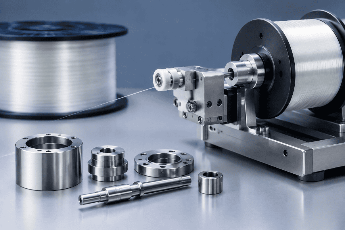
광섬유 Proof Test 장비 부품은 완성된 광섬유가 검증되고 재포장되는 지점에 위치하므로, 그곳에서 발생하는 모든 기계적 문제는 전체 생산 일정에 영향을 미칩니다. 광섬유는 캡스턴, 시브, 가이드 롤러, 댄서 어셈블리를 통해 제어된 장력으로 인출되며, 단 하나의 마모되거나 정렬이 어긋난 부품만으로도 슬립, 표면 손상 또는 잘못된 proof-test 경보가 발생할 수 있습니다. 따라서 신뢰할 수 있는 광섬유 proof test 장비 부품을 소싱하는 것은 가장 저렴한 교체품을 찾는 것보다 각 부품을 하중 경로, 마모 모드, 정렬 요구사항에 맞추는 것이 더 중요합니다.
Proof-Test 및 Rewind 라인이 Draw 또는 Deposition 장비와 다른 점
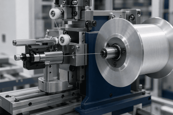
Proof-test 장비는 광섬유가 최소 강도 사양을 충족하는지 검증하기 위해 제어된 인장 하중을 가하는 반면, rewind 기계는 제어된 장력과 속도로 광섬유를 한 스풀에서 다른 스풀로 이동시킵니다. 두 공정 모두 열적 공정이 아닌 기계적 공정이며, OVD, VAD 또는 MCVD 프리폼 제조에서 볼 수 있는 고온 버너나 deposition 토치를 사용하지 않습니다. 이러한 구분이 중요한 이유는 고온 deposition 환경에서 우수한 성능을 발휘하는 부품이 상온 장력 및 가이드 시스템에 자동으로 적합한 선택이 되는 것은 아니기 때문입니다.
OVD 또는 VAD 장비와 비교할 때, proof-test 및 rewind 하드웨어는 주로 다음과 같은 부품들로 구성되는 경향이 있습니다:
- 회전 접촉 부품 — 캡스턴, 시브, 가이드 롤러, 풀리 어셈블리
- 장력 제어 요소 — 댄서 암, 로드셀 장착 고정구, 브레이크 또는 클러치 인터페이스 부품
- 광섬유 처리 표면 — 가이드 홈, 세라믹 또는 코팅 접촉면, 입출구 부싱
- 스풀 및 보빈 인터페이스 — 척, 어댑터, 클램핑 칼라, 권취 맨드릴
- 보빈 교체 시 사용되는 커터 및 클램프 메커니즘 부품
이러한 부품들은 나출 또는 코팅된 광섬유와 직접 상호작용하기 때문에, 표면 조도, 동심도, 홈 형상이 단순한 강도보다 더 중요할 때가 많습니다. 회전은 정확하지만 접촉면이 거친 롤러도 광섬유를 손상시킬 수 있으며, 완벽하게 매끄러운 롤러라도 축에서 벗어나 장착되면 proof-test 데이터에 노이즈로 나타나는 장력 변동을 유발할 수 있습니다.
프리폼 제조도 지원하는 유지보수 팀은 두 영역을 분리하여 유지해야 합니다. 마모 메커니즘, 청정도 요구사항, 심지어 체결류까지도 충분히 다르기 때문에, 광섬유 proof test 장비 부품과 deposition 하드웨어 간에 부품을 교차 적용하면 일반적으로 문제를 해결하기보다 더 많은 문제를 야기합니다.
일반적인 고장 지점 및 조사 방법
Proof-test 또는 rewind 라인이 일관성 없는 결과를 생산하기 시작할 때, 원인은 전기적 문제보다 기계적 문제인 경우가 많습니다. 다음 섹션에서는 근본 원인을 확인하기 전에 부품을 교체하면 문제가 다음 부품으로 단순히 이동할 수 있으므로, 가능한 원인과 확인된 진단을 구분합니다.
장력 불안정 및 잘못된 proof-test 판독값
가능한 원인: 마모된 가이드 롤러 베어링, 손상된 댄서 피벗, 캡스턴 표면의 오염, 또는 이동된 로드셀 마운트.
확인 방법: 양호한 것으로 확인된 광섬유를 라인에 통과시키고 각 센서에서 측정된 장력을 비교하여 장력 구역을 격리합니다. 장력이 롤러 회전에 따라 변하지만 광섬유 등급에 따라 변하지 않으면 롤러가 유력한 원인입니다. 베어링의 거칠기 또는 축방향 유격을 검사하고, 롤러 홈에 박힌 이물질이 없는지 확인합니다. 기계적 변화 없이 로드셀 판독값이 드리프트하는 경우, 로드셀 자체를 교체하기 전에 마운트와 케이블 배선을 점검해야 합니다.
이 구역이 기계에서 대부분의 작업을 수행하기 때문에, 이곳의 작은 정렬 오류는 계획된 정비 중 광섬유 proof test 장비 부품이 거부되는 가장 흔한 근본 원인입니다. 롤러 면에서 측정한 다이얼 인디케이터 판독값은 HMI에서 전기적 문제로 보이는 문제를 종종 드러냅니다.
광섬유 표면 손상 또는 코팅 자국
가능한 원인: 긁히거나 치핑된 가이드 표면, 정렬이 어긋난 입구 부싱, 또는 광섬유 직경과 더 이상 일치하지 않는 롤러 홈.
확인 방법: 의심되는 경로를 통해 짧은 길이의 광섬유를 통과시키고 각 접촉점에서 확대하여 검사합니다. 광섬유 길이를 따라 일관된 위치에서 나타나는 손상은 특정 롤러 또는 부싱을 가리킵니다. 시각적으로 유사한 부품이 호환된다고 가정하지 말고 도면과 대조하여 홈 프로파일을 확인합니다.
Rewind 중 스풀 또는 보빈 슬립
가능한 원인: 마모된 척 조, 변형된 클램핑 칼라, 또는 보빈 허브와 더 이상 일치하지 않는 어댑터.
확인 방법: 보빈과 척을 표시하고 짧은 rewind 사이클을 실행하여 상대적 움직임을 확인합니다. 슬립이 확인되면 교체품을 주문하기 전에 척과 허브 치수를 원래 도면과 대조하여 측정합니다. 많은 경우 해결책은 전체 척 어셈블리가 아닌 새 어댑터 또는 칼라입니다.
교체 시 커터 또는 클램프 결함
가능한 원인: 무뎌진 블레이드, 마모된 피벗, 또는 일관된 힘을 더 이상 유지하지 못하는 클램프.
확인 방법: 블레이드 날과 피벗의 마모를 검사하고, 장비 문서와 대조하여 클램프 힘을 확인합니다. 커터 및 클램프 어셈블리는 종종 소모품으로 취급되므로, 전체 어셈블리를 교체해야 하는지 아니면 블레이드만 교체하면 되는지 확인할 가치가 있습니다.
권취 및 보빈 교체도 처리하는 라인의 경우, 다음과 같은 부품 광섬유 와인더 커터 어셈블리 부품 은 클램프와 커터가 함께 마모되기 때문에 종종 한 세트로 교체됩니다.
Rewind 기계 부품의 재료 및 설계 선택
Fiber rewind machine components rarely fail for lack of strength. They fail because a material choice did not match the contact conditions. When evaluating a replacement or specifying a new part, consider:
- Contact material: Surfaces that touch fiber should be chosen for smoothness, wear resistance, and compatibility with the coating. Metals that can shed particles or develop sharp edges are poor choices for direct fiber contact.
- Coating or surface treatment: Coatings can improve wear life, but they must be applied consistently. An uneven coating can create a high spot that damages fiber.
- Bearing selection: Bearing type affects runout, drag, and service interval. High-speed rewind lines may need different bearings than low-speed proof-test stations.
- Alignment features: Pilot diameters, locating shoulders, and keyways are what keep a roller or capstan running true. These features should be inspected and specified on the drawing, not assumed.
- Balance and concentricity: For rotating parts, imbalance shows up as vibration, which in turn shows up as tension noise. Concentricity tolerances should reflect the operating speed of the line.
- Cleaning and changeover: Parts that are easy to remove and clean reduce the risk of contamination being pushed into a fiber path.
Aluminum is frequently used for structural brackets and non-contact housings, but it is generally a poor choice for direct fiber contact surfaces unless a suitable surface treatment is applied. Where aluminum components are relevant to a rewind or handling assembly, they should be evaluated on function and surface condition rather than assumed suitable. The same principle applies across aluminum VAD burner hardware and other precision components: material suitability depends on the specific contact, load, and environment.
Contamination control is another design variable that is easy to overlook. A part that traps fiber dust or coating debris will eventually transfer that material back onto the fiber path, creating defects that appear intermittent and are difficult to trace. Whenever possible, specify radii, relief grooves, and drainage features that let debris fall away instead of collecting near a contact surface. That approach is standard practice in precision fiber handling, and it is the same logic behind our guide to 광섬유 가이드 롤러 샤프트 and their assembly checks.
비용, 리드 타임, 마모 수명의 균형
Purchasing teams often face pressure to reduce the unit cost of optical fiber proof test equipment parts, but the cheapest option rarely wins over a full maintenance cycle. A low-cost roller that wears twice as fast may require two replacements and two line stoppages in the time a properly specified part lasts. When comparing quotes, it helps to evaluate cost per operating hour rather than cost per piece, and to ask suppliers how the material and tolerances were selected for the application.
Lead time matters just as much as price on a line that cannot run without a specific component. Keeping one or two wear-critical spares on the shelf is usually cheaper than an expedited custom run, and it gives maintenance time to inspect the failed part properly instead of reinstalling a marginal one.
교체품 소싱 요청에 포함해야 할 사항
Rewind and proof-test parts are often non-standard, so a clear sourcing request saves time on both sides. A useful request typically includes:
- 도면 또는 스케치 with critical dimensions, tolerances, and surface finish requirements
- Material and surface treatment requirements, or a description of the operating conditions if no material is specified
- Quantity and application — prototype, spare, or production replacement
- Interface details — shaft diameter, mounting pattern, gas or fluid connections if applicable, and any keyway or locating features
- Operating conditions — speed, tension range, fiber type, and ambient environment
- Reference part number or photo of the existing component, where available
When an original drawing is not available, reverse engineering from a physical sample is often feasible. This usually involves measuring critical dimensions, identifying material and any surface treatment, and confirming fit with the mating parts before production. For non-standard or obsolete rewind components, custom machining services can produce parts from drawings or samples, provided the dimensions and application requirements are clearly defined.
It is also worth checking whether the component is part of a broader assembly. A guide roller that appears to be a standalone part may actually be one element of a tension-control module, and replacing only part of the module can leave a wear mismatch. Where a range of replacement options is needed, browsing the overall optical fiber equipment parts range can help confirm whether a standard item exists before committing to a custom run.
Specification details that are commonly forgotten include plating thickness, allowable runout after assembly, and the matching surface finish of the mating bore. Adding these to the request avoids a situation where a part arrives within its own drawing tolerance but still does not assemble correctly with the rest of the line. If tolerances on optical fiber proof test equipment parts are not clearly stated, suppliers may default to general machining tolerances that are too loose for a fiber contact application.
Rewind 부품 수명을 연장하는 유지보수 관행
Rewind and proof-test parts are mechanical rather than thermal, so maintenance practices differ from burner and torch care. Practical measures include:
- Recording runout and tension readings at each scheduled service so trends are visible before a failure occurs
- Inspecting fiber contact surfaces for scoring, embedded debris, or coating buildup
- Checking roller and capstan bearings for play, noise, or temperature rise
- Verifying that replacement parts match the original drawing before installation
- Keeping spares for the highest-wear items so a fault does not stop the line
Where the same fiber path handles multiple fiber types or diameters, it is worth reviewing whether the guide and roller geometry still suits the current product mix. A line that has changed fiber specifications may be running with components sized for a different range, which can cause tension variation even when the parts themselves are in good condition.
For readers who want to understand how mechanical parts degrade across different fiber processes, the Telecommunications Industry Association publishes the fiber optic test procedures that define many proof-test and measurement methods. Comparing the equipment requirements in that standard with the condition of the line’s mechanical hardware is a practical way to spot a drifting process before it produces out-of-spec fiber.
Service records are most useful when they are tied to specific part numbers and positions on the line. Recording which roller, bushing, or chuck was replaced, and at what running hours, makes it possible to compare wear rates between suppliers and to justify a change in material or coating when the data supports it.
납품 후 적합성 및 품질 검증
Receiving inspection is the last chance to catch a problem before it reaches the line. For optical fiber proof test equipment parts, a light but consistent inspection routine pays for itself quickly.
- Confirm the part number, revision, and quantity against the purchase order and drawing
- Check critical diameters, groove profiles, and locating features with calibrated instruments
- Inspect contact surfaces for tool marks, burrs, coating defects, or embedded debris
- Verify that any keyway, shoulder, or pilot diameter seats correctly on the mating part
- Rotate assembled rollers and capstans to confirm smooth running with no detectable play
Where a batch of replacement parts is being introduced for the first time, it is worth running a short qualification trial on the line and comparing tension readings against the previous baseline. This catches subtle differences in balance or surface finish that are hard to see by eye but show up clearly in measurement data.
자주 묻는 질문
Proof-test 및 rewind 부품을 OVD 토치 또는 버너 부품과 호환하여 사용할 수 있습니까?
No. Proof-test and rewind components operate at room temperature under mechanical tension and contact loads, while OVD and VAD burners operate under high-temperature deposition conditions. The materials, tolerances, and surface requirements are different, and parts should be specified for their actual application.
Rewind 롤러를 교체해야 하는지 아니면 조정만 하면 되는지 어떻게 알 수 있습니까?
Measure runout and inspect the contact surface. If runout is within the equipment specification and the surface is undamaged, adjustment or cleaning may be sufficient. If runout exceeds the specification or the surface shows scoring or embedded debris, replacement is usually the more reliable option.
맞춤형 rewind 부품을 견적 받으려면 어떤 정보가 필요합니까?
A drawing or sample, material and surface treatment requirements, critical dimensions and tolerances, quantity, and a description of the operating conditions. If a drawing is unavailable, a physical sample and the mating dimensions are usually enough to begin.
알루미늄 부품이 광섬유 접촉면에 적합합니까?
Aluminum is often used for structural and non-contact components where weight and machinability matter. For direct fiber contact, the surface condition and any applied treatment are the deciding factors, so the material should be selected based on the actual contact and wear requirements rather than on the metal alone.
광섬유 proof test 장비 부품은 설치 전에 어떻게 보관해야 합니까?
Keep them in original packaging or clean protective covers until the line is ready, away from dust, moisture, and metalworking areas. Contact surfaces should be inspected again immediately before installation, since a part that sat open on a bench can pick up debris that is difficult to see.
광섬유 proof test 장비 부품은 얼마나 자주 교체해야 합니까?
There is no universal interval, because it depends on line speed, tension, fiber coating, and hours per week. The practical approach is to trend runout and tension readings at each service and replace an optical fiber proof test equipment parts item when the trend shows drift, rather than waiting for a failure or following a fixed calendar schedule.
다음 단계
If a proof-test or rewind component is causing tension variation, fiber damage, or repeat changeover faults, the fastest route to a reliable replacement is to share the drawing, dimensions, material requirements, and operating conditions with the supplier. You can discuss your component requirements directly, including reverse-engineering from a sample where no drawing exists, and confirm fit against the mating parts before production begins.
Reliable optical fiber proof test equipment parts come from clear specifications and confirmed fits, not from guesswork. Whether the need is a single replacement roller or a batch of custom rewind mechanical parts, matching the component to its actual load path and contact conditions is what keeps a proof-test or rewind line running at spec.
