
Wissen
Preform-Drehmaschinen-Futterkomponenten: Kundenspezifische Bearbeitung und Werkstückaufspannungsprüfungen
Okt.
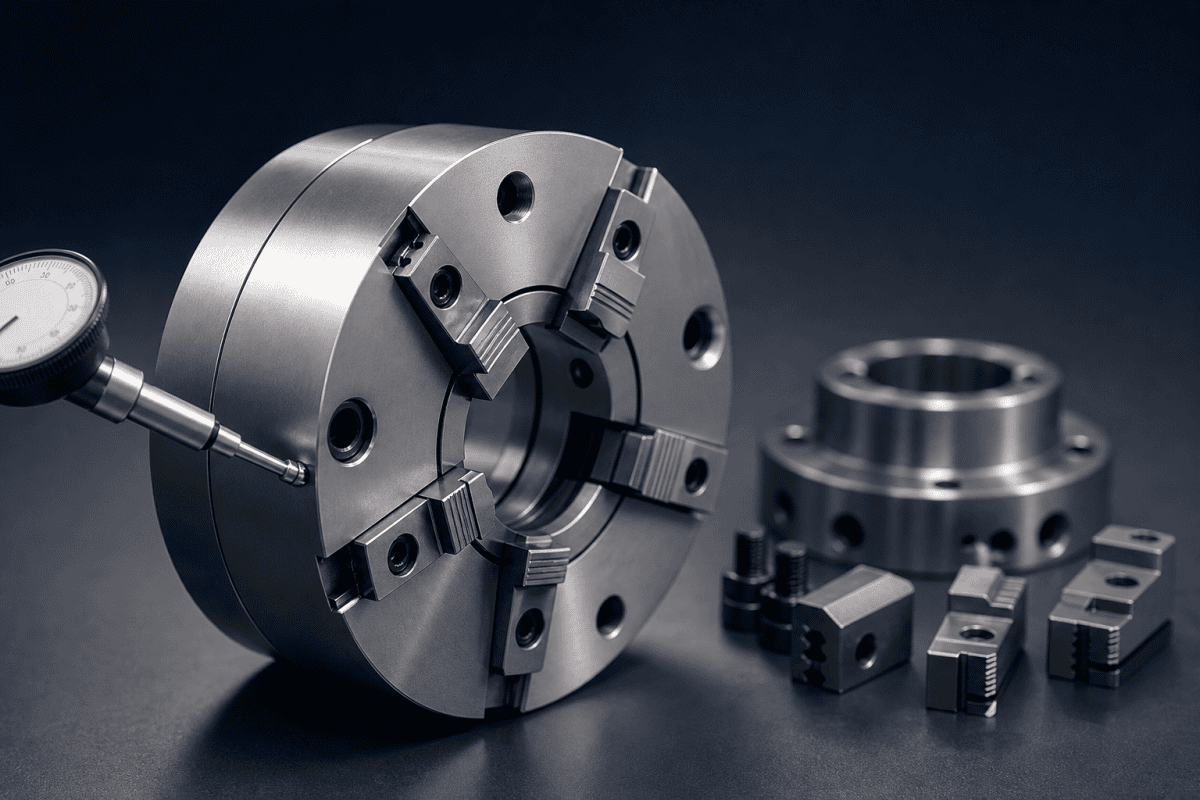
Preform-Drehfutterkomponenten befinden sich an dem Punkt, an dem Präzisions-Werkstückspannung auf Hochtemperaturabscheidung trifft. Für Ingenieure, die OVD-, VAD- oder MCVD-Prozesse betreiben, ist das Futter nicht nur eine Montagevorrichtung — es legt die Rotationsachse fest, auf die sich das Brenner-, Torch- oder Traversiersystem während des gesamten Laufs bezieht. Wenn Futterbacken verschleißen, Auflageflächen sich verschlechtern oder ein Ersatzbackensatz ohne vollständige Maßdaten gefertigt wird, zeigt sich die resultierende Rundlaufabweichung als Rußabscheidungsasymmetrie, Konizitätsvariation oder inkonsistente Brechungsindexprofile, lange bevor jemand die Werkstückspannung verdächtigt.
Dieser Artikel behandelt, was an Preform-Drehfutterkomponenten zu prüfen ist, wie kundenspezifische Preform-Futterteile vor der Bestellung zu bewerten sind und welche Informationen eine Werkstatt benötigt, um Ersatz-Werkstückspannvorrichtungen herzustellen, die der ursprünglichen Konstruktionsabsicht entsprechen.
Was Preform-Drehfutterkomponenten tatsächlich leisten
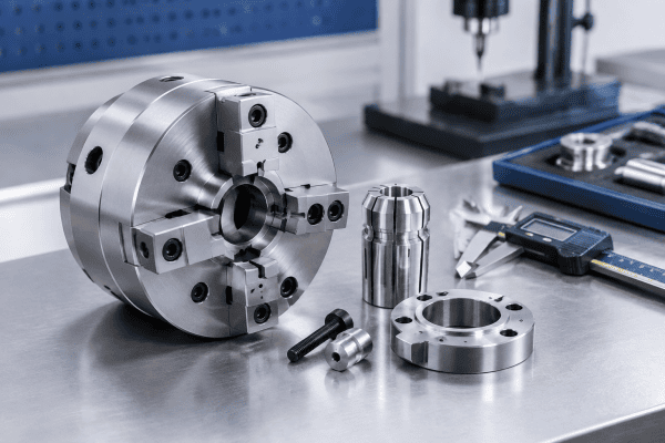
Eine Preform-Drehmaschine hält einen Glas-Bait-Stab, Target-Stab oder Startrohr, während Brenner Ruß abscheiden oder während die Preform konsolidiert und gestreckt wird. Das Futter — ob ein Dreibacken-SpiralFutter, ein spannzangenartiger Verschließer oder eine kundenspezifische Split-Clamp-Konstruktion — muss drei Dinge gleichzeitig leisten:
- Drehmoment ohne Schlupf bei der Betriebsdrehzahl übertragen
- Radialen Rundlauf innerhalb der vom Abscheideprozess geforderten Toleranz aufrechterhalten
- Die Spannposition so genau wiederholen, dass die Variation von Preform zu Preform kontrolliert bleibt
Diese Funktionen sind voneinander abhängig. Ein Futter, das sicher greift, aber eine axiale Neigung einbringt, erzeugt eine gekrümmte Preform-Achse. Ein Futter mit ausgezeichnetem Rundlauf, aber unzureichender Spannkraft kann Mikroschlupf während der Beschleunigung zulassen, was sich als Oberflächenmarkierungen oder lokalisierte Durchmesservariation zeigt.
Die beteiligten Komponenten umfassen typischerweise Backeneinsätze oder Kontaktpads, Backenträger, Spiralplatten oder Spannringe, Grundplatten, Adapterplatten und manchmal kundenspezifische Distanz- oder Ausrichtungsmerkmale, die das Futter auf der Drehmaschinenspindel positionieren. Jede dieser Komponenten kann unabhängig verschleißen, sich verformen oder beschädigt werden. Der Gesamtzustand dieser Preform-Drehfutterkomponenten bestimmt, wie wiederholbar der Abscheideprozess sein kann.
Prüfpunkte für Präzisions-Werkstückspannkomponenten
Vor der Bestellung von Ersatzteilen ist es hilfreich festzustellen, welche Komponente tatsächlich das Problem verursacht. Eine gesamte Futterbaugruppe zu ersetzen, wenn nur die Kontaktpads verschlissen sind, ist teuer und unnötig; umgekehrt wird das Fertigen neuer Backen für eine verformte Spiralplatte die Konzentrizität nicht wiederherstellen.
Backenkontaktflächen und Einsätze
Backeneinsätze, die das Glas oder den Trägerstab berühren, sind das häufigste Verschleißteil. Achten Sie auf:
- Kontaktmuster: Eine gleichmäßige, vollbreite Kontaktspur entlang der Backenstirnfläche deutet auf gleichmäßige Belastung hin. Konzentrierte Markierungen an einem Ende weisen auf Winkelversatz oder eine verbogene Backe hin.
- Eingebettete Partikel: Glassplitter, Ruß oder abrasiver Schmutz, der in weiches Backenmaterial eingepresst wird, kann den Stab verkratzen und die Griffkonsistenz verringern.
- Verformung: Übermäßiges Anziehen oder thermische Belastung kann die Backenstirnfläche aufweiten oder pilzförmig verformen, wodurch die effektive Kontaktfläche verringert wird.
- Materialzustand: Einsätze können je nach Anwendung aus Aluminium, Bronze, Polymerverbundwerkstoffen oder anderen Materialien gefertigt sein. Die Materialwahl sollte auf Kontaktdruck, Temperatur am Futter, Kontaminationsrisiko und darauf basieren, ob der Einsatz leicht nachgeben muss, um das Glas nicht zu beschädigen. Aluminium wird manchmal für leichteren Kontakt oder dort verwendet, wo Wärmeleitfähigkeit hilft, aber es sollte nicht als für jede Futterposition geeignet angenommen werden — siehe Aluminium-OVD-Teile für Kontext dazu, wo Aluminiumkomponenten typischerweise eingesetzt werden.
Spiralplatten, Spannringe und Betätigungsflächen
SpiralFutter stützen sich auf eine Spiralplatte, die alle Backen gleichzeitig bewegt. Verschleiß an den Spiralzähnen erzeugt ungleichmäßigen Backenvorschub, was bedeutet, dass der Stab nicht zentriert ist, selbst wenn die Backen scheinbar gleichmäßig schließen. Prüfen Sie auf:
- Sichtbaren Verschleiß oder Fressspuren an der Spiralspirale
- Umkehrspiel beim Richtungswechsel der Backen
- Positionsvariation von Backe zu Backe beim Schließen auf einem bekannten Rundnormal
Bei spannzangenartigen oder Split-Clamp-Futtern prüfen Sie die Schließkonus und den Biegebereich auf Risse, bleibende Verformung oder ungleichmäßigen Kontakt.
Grundplatten und Spindelschnittstellen
Die Grundplatte oder der Adapter, der das Futter an der Drehmaschinenspindel montiert, legt die Referenzebene fest. Schmutz, Grate oder Passungsrost an dieser Schnittstelle können das gesamte Futter verkippen. Selbst ein kleiner Winkelfehler an der Grundplatte wird am fernen Ende einer langen Preform verstärkt.
Prüfen Sie die Montagefläche auf Ebenheit, den Passungsdurchmesser auf Passung und die Schraubenlöcher auf Aufweitung oder Gewindeschäden. Bei kundenspezifischen Futtern verifizieren Sie, dass die Passung ohne Kraftaufwand und ohne wahrnehmbares Spiel auf den Spindelstock passt.
Rundlaufmessung
Der radiale Rundlauf sollte bei montiertem und betätigtem Futter gemessen werden, wie es in der Produktion der Fall wäre. Verwenden Sie eine Messuhr auf einer bekannten zylindrischen Oberfläche — einem Prüfdom oder einem geschliffenen Normal — sowohl an der Futterstirnfläche als auch in einem Abstand, der die Arbeitsposition der Preform repräsentiert. Zeichnen Sie den Rundlauf an mehreren Rotationspositionen auf. Wenn der Rundlauf mit der Backenposition statt mit dem Rotationswinkel variiert, liegt das Problem in den Backen oder der Spirale; wenn er sich einmal pro Umdrehung wiederholt, kann das Problem in der Spindel, der Grundplatte oder dem Futterkörper liegen.
Prüfungen der Werkstückspannschnittstelle über das Futter hinaus
Das Spannfutter ist nur ein Element der Werkstückaufnahmeschnittstelle. Der Reitstock, die Setzstockbacken und jede Zwischenstütze beeinflussen ebenfalls die Achse des Rohlings. Wenn das Spannfutter zentriert ist, der Reitstock jedoch versetzt ist, wird sich der Rohling verziehen. Prüfen Sie den Rundlauf der Reitstockzentrierspitze, den Zustand der Setzstockauflagen und die Ausrichtung zwischen Spindelstock und Reitstock über den gesamten Verfahrweg. Bei Drehmaschinen, die bewegt oder neu ausgerichtet wurden, sollte diese Ausrichtung erneut überprüft werden, bevor das Spannfutter als Ursache vermutet wird.
Der Spindelkegel und der Zustand der Zugstange sind ebenfalls wichtig für Spannfutter im Spannzangenstil. Ein verschlissener Kegel oder eine gedehnte Zugstange verringert die Spannkraft und kann dazu führen, dass die Spannzange außeraxial sitzt. Messen Sie die Zugstangenverlängerung und prüfen Sie den Kegel auf Riefen oder Passungsrost.
Für Ingenieure, die mit der Ausrichtung von Abscheidungsbrennern arbeiten, ist die Werkstückaufnahmeschnittstelle Teil einer größeren Ausrichtungskette. Der Artikel über optische Faserrohling-Ausrüstung und Abscheidungsbrenner-Teile behandelt verwandte technische und Beschaffungsfragen, die häufig im Zusammenhang mit Spannfutterarbeiten auftreten.
Wann kundenspezifische Preform-Futterteile gefertigt werden sollten
Kundenspezifische Rohling-Spannfutterteile werden notwendig, wenn Originalkomponenten nicht mehr verfügbar sind, wenn das Spannfutter für eine bestimmte Drehmaschine oder Rohlinggröße modifiziert wurde oder wenn die bestehende Konstruktion im Einsatz nicht standhält. Kundenspezifische Bearbeitung ist auch üblich, wenn ein Produktionsteam die Geometrie der Kontaktauflagen für einen anderen Stabdurchmesser ändern oder die Markierung auf dem Glas reduzieren möchte.
Typische kundenspezifische Teile umfassen:
- Replacement jaw inserts with modified contact geometry or material
- Adapter plates for mounting a chuck on a different spindle interface
- Split-clamp halves machined to a specific preform diameter
- Spacer rings and alignment sleeves that set axial position
- Non-standard backplates where the original is damaged or unavailable
For any of these, OEM/ODM machining services can produce parts from drawings, samples, or measured dimensions. The critical input is not the part name but the functional requirements: what the part must locate, what load it carries, what temperature it sees, and what material is appropriate.
Informationen, die für ein Angebot für eine kundenspezifische Futterkomponente bereitzustellen sind
A machine shop cannot produce a reliable workholding component from a description alone. Useful inputs include:
- Drawings or sketches with critical dimensions, tolerances, and datums. If no drawing exists, provide a physical sample or detailed measurements.
- Material specification or the material of the original part. If the original material is unknown, describe the operating environment — temperature, humidity, contact with glass, cleaning agents — so the shop can recommend a suitable alloy or polymer.
- Interface dimensions: spindle register diameter, bolt circle, jaw slot dimensions, and any keyway or locating feature.
- Operating conditions: rotational speed range, clamping force, rod diameter and weight, and whether the chuck sees radiant heat from the burner or torch.
- Quantity and lead time expectations, recognizing that prototype quantities and production quantities may follow different processes.
- Inspection requirements: which dimensions are critical, and whether a dimensional report is needed.
Photographs of the installed chuck, the worn area, and the spindle interface are often as valuable as a drawing because they show how the part actually fits and wears.
Reverse Engineering anhand einer vorhandenen Komponente
When drawings are unavailable, reverse engineering from a sample is a practical route. Accuracy depends on the condition of the sample and the measurement methods used. A worn jaw insert, for example, may no longer represent the original contact geometry, so the shop must distinguish between intentional features and wear. Hardness testing, material analysis, and careful measurement of unworn reference surfaces help separate design intent from service damage.
For chucks used on SG Controls or similar MCVD lathes, the mounting interface and jaw geometry may be specific to that platform. The guide to SG Controls MCVD lathe spare parts describes typical custom machined holders and carriage components, which provides useful context for how workholding interfaces are documented and reproduced.
If the original chuck design used interchangeable inserts, it may be possible to standardize on a new insert geometry that improves grip or reduces glass marking without modifying the carrier. This kind of incremental change is often more cost-effective than a complete chuck redesign.
Werkstückspannprüfungen vor und nach dem Austausch
Installing a new or re-machined chuck component without verification can introduce a new error. A simple sequence helps confirm that the workholding is not the source of process variation:
- Clean all interfaces before assembly. Soot, glass dust, and dried lubricant are common causes of tilt and runout.
- Check register fit by hand. The chuck should seat fully without rocking.
- Torque fasteners evenly in a crossing pattern to avoid distorting the backplate.
- Measure runout at the chuck and at working distance after assembly, using a gauge that represents the preform diameter.
- Clamp a test rod and check for axial tilt by measuring at two points along the rod.
- Run a short deposition or rotation test if the process allows, and compare the result against a known-good baseline.
If runout changes after clamping, the issue may be in the jaw contact or scroll rather than the spindle. If runout is constant but high, the backplate or spindle interface is the more likely source.
Workholding problems sometimes present as deposition problems. If soot deposition becomes asymmetric or the preform develops a taper, the chuck may be contributing. Related diagnostic logic is discussed in the article on refractive index profile drift and burner concentricity, and in the guide to preform end-taper thermal stress, but the chuck should be checked before adjusting burner parameters.
Document the baseline measurements. A simple log of runout at the chuck face and at working distance, recorded after each rebuild, makes it easier to distinguish sudden changes from gradual wear. It also gives the machining team a reference when producing replacement preform lathe chuck components.
Material- und Konstruktionsüberlegungen für Futterkomponenten
Material selection for precision workholding components depends on the specific function:
- Contact pads and jaw inserts: Must balance grip, wear resistance, and protection of the glass surface. Hard materials resist wear but may mark or chip the rod; softer materials protect the glass but wear faster and may embed debris.
- Structural components (backplates, jaw carriers): Need dimensional stability and adequate stiffness. Thermal expansion mismatch between the chuck and the spindle can change runout as the lathe warms up.
- Components exposed to heat: If the chuck is close to the deposition zone, radiant heating may cause expansion or material degradation. The appropriate material depends on the actual temperature at that location, which should be measured rather than assumed.
Because these requirements vary by lathe, preform size, and process, it is worth reviewing the range of optical fiber equipment parts available as standard items before committing to a fully custom design. In some cases a standard component can be adapted; in others, custom machining is the more reliable route.
Design choices also affect maintainability. Inserts that can be replaced without removing the chuck from the spindle reduce downtime, and clearly defined datums make it easier to verify alignment after service. For lathes that run multiple preform sizes, interchangeable jaw sets or adjustable stops can reduce changeover time while preserving the reference surfaces that keep runout predictable.
Tolerances should match function. Over-tight tolerances on non-critical features increase cost without improving performance, while loose tolerances on locating surfaces directly affect runout. The drawing should identify which dimensions are functional and which are reference only.
Wie Preform-Drehfutterkomponenten in den weiteren Abscheideprozess passen
The chuck does not operate in isolation. It interacts with the burner traverse, the gas delivery system, and the exhaust flow. Runout in the chuck changes the distance between the burner face and the glass surface, which in turn affects deposition efficiency and soot density. Even a small eccentricity can produce a periodic variation that looks like a burner pulsing problem.
For this reason, maintenance planning should treat the workholding and the deposition torch as a single alignment chain. When a burner is replaced or repositioned, it is worth confirming that the chuck is still centered and that the preform axis has not shifted. Conversely, when a chuck is rebuilt, the burner alignment should be re-checked before the next production run.
Burner components themselves are subject to wear and can introduce their own variation. Sourcing guides such as the Nextrom VAD burner replacement parts guide or the overview of OVD-Brennerteile explain how those consumables are specified and replaced. Keeping both the workholding and the burner in specification reduces the chance of misattributing a deposition defect to the wrong subsystem.
For processes that require precise refractive index profiles, the combination of chuck runout, burner concentricity, and traverse stability determines the final result. Measuring each contribution separately is the only reliable way to isolate a problem when the profile drifts.
FAQ
Wie oft sollten Preform-Drehfutterkomponenten geprüft werden?
Inspection frequency depends on operating hours, rotational speed, and contamination levels. A practical approach is to check jaw contact patterns and runout at each scheduled maintenance interval, and to inspect immediately after any incident that could have overloaded the chuck — a jam, a crash, or a preform break during rotation. Trending runout measurements over time is more useful than a single check because it reveals gradual wear. Many facilities find that inspecting these preform lathe chuck components at every major maintenance window is sufficient, with additional checks after any abnormal event.
Können verschlissene Futterbacken repariert werden, anstatt ersetzt zu werden?
In some cases, jaw inserts can be re-machined or replaced while the jaw carrier is reused. This depends on whether the carrier itself is distorted and whether re-machining would remove too much material or change the clamping geometry. For scroll plates with worn teeth, repair is rarely practical, and replacement is usually more reliable. A machine shop can assess the worn part and advise based on measured condition. When repair is chosen, the resulting preform lathe chuck components should be re-measured to confirm that clamping geometry still meets the original specification.
Was ist die häufigste Ursache für Rundlaufabweichungen in einem Preform-Drehfutter?
Contamination or damage at the spindle-to-backplate interface is one of the most frequent causes, followed by uneven jaw wear. Because the interface error is amplified over the length of the preform, a small amount of debris or a burr can produce significant runout at the working position. Cleaning and inspecting this interface is a logical first step before suspecting the chuck body or jaws. If the interface is clean and the runout persists, then the jaws, scroll, or spindle bearings become the next candidates.
Kann OVDParts eine Futterkomponente anhand eines Musters per Reverse Engineering nachbauen?
Reverse engineering from a physical sample is possible when the sample is complete enough to measure critical features and when the material can be identified or a suitable substitute specified. The more dimensional and functional information provided, the more reliable the result. For components where the sample is worn or incomplete, drawings and interface measurements from the lathe are important supplements. In many cases, a combination of a worn sample and a few key measurements from the machine is enough to produce replacement preform lathe chuck components that restore original performance.
Nächster Schritt
If you are evaluating replacement preform lathe chuck components or planning a custom workholding project, gather the drawings, sample measurements, material details, and operating conditions described above. Sharing these inputs with the manufacturer allows a more accurate assessment of feasibility and cost. To discuss a specific component, contact our team with your dimensions, material requirements, and the operating conditions the part must withstand.
For broader context on preform equipment parts and how they are sourced, the ISO 10110 optical drawing standard provides useful guidance on specifying tolerances for optical components, which can inform how you document critical dimensions on your own drawings.
