
지식
광섬유 프리폼 장비용 프리폼 버너 장착 플랜지 및 맞춤형 버너 어댑터: 완벽한 소싱 및 유지보수 가이드
10월
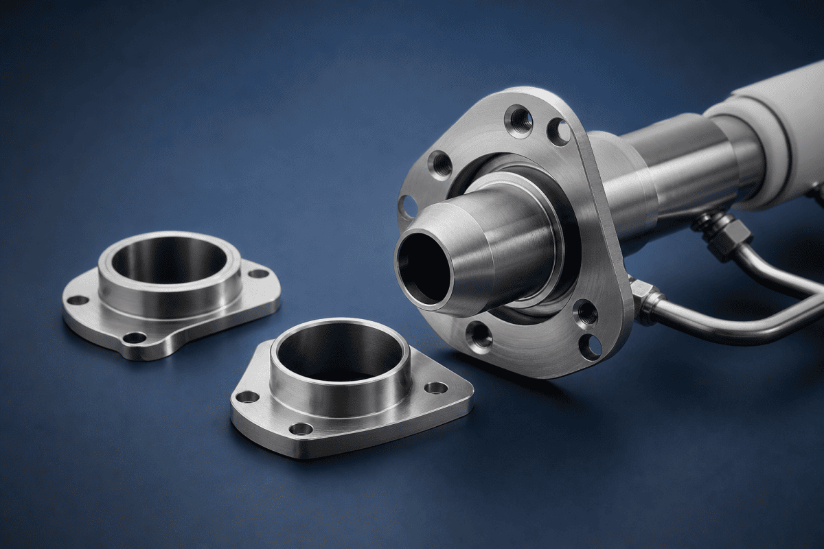
Preform 버너 장착 플랜지와 맞춤형 버너 어댑터는 버너 어셈블리와 선반 캐리지 사이의 인터페이스에 위치하며, 증착 품질이 드리프트할 때 엔지니어가 가장 마지막에 점검하는 부품인 경우가 많습니다. 이들은 그을음이나 유리에 직접 닿지 않기 때문에 치수적으로 안정적이라고 가정됩니다. 실제로는 휘어지거나, 부식되거나, 교체 토치에 맞추기 위해 심(shim)이 삽입된 Preform 버너 장착 플랜지는 버너 축을 1밀리미터의 일부만큼 이동시킬 수 있으며, 이는 화염 형상, Preform 증착, 그리고 그 결과로 얻어지는 굴절률 프로파일을 교란하기에 충분합니다. 이 글에서는 이러한 부품이 광섬유 장비 장착 부품 무엇을 하는지, Preform 버너 장착 플랜지를 어떻게 점검해야 하는지, 그리고 교체품 또는 맞춤형 버너 어댑터 를 OVD, VAD, MCVD 시스템에 맞게 정확하게 지정하는 방법을 설명합니다.
Preform 버너 장착 플랜지의 실제 역할
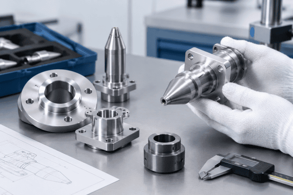
Preform 버너 장착 플랜지는 버너 또는 토치 본체를 Preform에 대해 고정되고 반복 가능한 위치에 유지하는 기계적 브래킷입니다. 기계 설계에 따라 캐리지 플레이트에 볼트로 체결되거나, 리니어 레일 어셈블리에 클램프되거나, 가공된 기준면에 인덱싱될 수 있습니다. 그 역할은 단순히 무게를 지지하는 것이 아닙니다. 적절하게 설계된 Preform 버너 장착 플랜지는 다음을 충족해야 합니다:
- 열 사이클 전반에 걸쳐 버너-Preform 거리 및 각도 정렬 유지
- 풀림이나 크리프 없이 캐리지 이동으로 인한 진동에 저항
- 해당되는 경우 가스 공급 라인 및 냉각 연결부를 위한 밀봉 또는 안내 경로 제공
- 설정 위치를 잃지 않고 버너를 분리 및 재설치 가능
증착 속도와 화염 형상은 이격 거리와 기울기에 민감하기 때문에, 플랜지 상태는 유지보수 항목이 아니라 공정 변수입니다. 문서화된 도면 없이 재가공되었거나 토치 교체 중 심(shim)이 누적된 Preform 버너 장착 플랜지는 공정이 검증된 형상을 변경시킵니다. 이것이 증착에 미치는 영향에 대한 배경은 버너 노즐 정밀도 및 Preform 수율에 관한 논의를 참조하십시오.
점검할 가치가 있는 장착 플랜지 고장 모드
Preform 버너 장착 플랜지는 치명적으로 고장 나는 경우가 드뭅니다. 유지보수 기간 중 간과하기 쉬운 방식으로 열화됩니다. 증착 균일성이나 프로파일 제어가 일관성을 잃을 때, 버너 자체를 의심하기 전에 다음을 점검하십시오.
열 변형 및 크리프
반복적인 가열 및 냉각 사이클은 Preform 버너 장착 플랜지의 잔류 응력을 완화할 수 있으며, 특히 플랜지가 얇거나, 체결구에 의해 과도하게 구속되거나, 차등 팽창을 고려하지 않고 장착된 경우에 그러합니다. 변형은 명백한 휨이 아니라 버너 기울기의 변화로 나타날 수 있습니다. 수 주에 걸쳐 점진적으로 나타나는 기울기는 설치 오류보다 크리프의 전형적인 증상입니다. 버너 화염 기울기에 대한 진단 접근법은 플랜지 관련 기울기를 노즐 마모 및 가스 불균형과 분리해주기 때문에 여기서 유용합니다.
부식 및 표면 열화
증착 영역 근처의 Preform 버너 장착 플랜지는 열, 응축, 미량의 공정 부산물에 노출될 수 있습니다. 접합면의 부식 생성물이나 산화 스케일은 버너 위치를 변화시키는 간극을 도입합니다. 체결구 구멍 주변의 피팅(pitting)은 클램핑력을 감소시켜 캐리지 가속 시 버너가 이동할 수 있게 합니다. 기준면에 보이는 스케일은 외관 문제가 아니라 치수 변화로 취급해야 합니다. 관련 부품 소싱 맥락은 다음을 참조하십시오 Nextrom OVD 토치 예비 부품.
체결구 및 인터페이스 마모
볼트 체결 조인트는 시간이 지남에 따라 예압을 잃습니다. 나사산 인서트가 당겨지고, 슬롯 구멍이 늘어나며, 다웰 핀이 보어를 마모시킵니다. Preform 버너 장착 플랜지가 체결구 내에서 움직일 수 있게 되면 반복성은 사라집니다 — 버너는 재설치할 때마다 다른 위치로 돌아갈 수 있습니다. 토크 값을 문서화하고 첫 번째 열 사이클 후에 재확인하는 것은 이를 조기에 포착하는 간단한 관행입니다. 이 등급의 하드웨어에 대한 일반적인 정비 지침은 OVD 및 VAD 버너 유지보수 가이드에 나와 있습니다.
인터페이스에서의 재질 불일치
교체용 Preform 버너 장착 플랜지가 원본과 다른 합금으로 만들어지면 열팽창과 강성이 달라집니다. 그것이 자동으로 문제가 되는 것은 아니지만, 부품의 온도 노출, 주변 하드웨어, 요구되는 위치 안정성에 대해 평가해야 합니다. 팽창 거동을 고려하지 않고 단순히 “고온용”이라는 이유만으로 재질을 선택하면, 교체가 해결하려 했던 바로 그 드리프트를 초래할 수 있습니다. 이것이 OEM/ODM 가공 서비스에 치수뿐만 아니라 원래 재질과 교체 사유를 알려야 하는 이유 중 하나입니다.
표준 플랜지로 충분하지 않을 때: 맞춤형 버너 어댑터
맞춤형 버너 어댑터는 버너와 기계가 더 이상 고유 인터페이스를 공유하지 않거나, Preform 버너 장착 플랜지를 필요한 구성으로 조달할 수 없을 때 필요해집니다. 일반적인 상황은 다음과 같습니다:
- 다른 장착 형상의 교체 버너 또는 토치 본체를 기존 캐리지에 장착
- 구형 선반에 최신 버너 설계를 개조 적용
- 자체 장착 설비가 필요한 계측기, 차폐체 또는 퍼지 경로 추가
- 여러 레거시 플랜지 변형을 하나의 표준 인터페이스로 통합
어댑터는 정밀 전환 부품이므로, 연결하는 구성 요소의 모든 공차 요구 사항을 그대로 승계합니다. 두 가지 원칙이 가장 중요합니다. 첫째, 어댑터는 버너의 설계된 방향과 이격 거리를 유지해야 하며, 그렇지 못할 경우 공정 레시피를 재검증해야 합니다. 둘째, 어댑터가 스택에서 가장 취약한 연결부가 되어서는 안 됩니다. 순응형 어댑터는 버너보다 먼저 변형되며, 이는 일반적으로 토치 본체가 균열되는 것보다 바람직하지만, 해당 애플리케이션에 충분한 강성을 갖추어야 합니다. 버너 제품군별로 어댑터가 어떻게 지정되는지에 대한 예시는 다음을 참조하십시오 OVD 버너 헤드 교체.
가스 통로를 포함하는 맞춤형 버너 어댑터는 추가적인 주의가 필요합니다. 내부 형상은 유량 분포에 영향을 미치며, 내부 전환부가 불량한 어댑터는 채널 간 압력 불균형을 초래할 수 있습니다. 이에 대한 원리는 다채널 토치의 압력 밸런싱 및 가스 유동 역학에서 다루고 있습니다. 맞춤형 버너 어댑터가 가스 경로를 변경하는 경우, 버너가 설계된 유량 조건을 여전히 충족하는지 확인하고, 모든 변경 사항을 장비 문서 및 자격을 갖춘 공정 담당자와 함께 검증하십시오.
Preform 버너 장착 플랜지 및 어댑터 점검 체크리스트
Use this sequence during planned maintenance or when deposition results shift unexpectedly. The same steps apply whether you are inspecting a standard preform burner mounting flange or a one-off adapter.
- Record the current position before disassembly — standoff, tilt, and any index marks. Photographs with a scale reference are more useful than memory.
- Check the reference faces for scale, galling, dents, or embedded debris. Clean and re-inspect; do not file a reference face flat without a drawing.
- Measure flatness and parallelism against the original drawing where one exists. Without a drawing, measure the interface that matters — the face that sets burner orientation.
- Inspect fastener holes and pins for elongation, ovality, and thread condition.
- Verify material and finish if the part is a replacement or has been repaired by a third party. Do not infer material from appearance alone.
- Re-torque after the first thermal cycle and confirm the burner has not moved.
- Correlate with process data — if profile drift or deposition changes track the flange condition, that is supporting evidence, not proof. Confirm by restoring a known-good geometry and repeating the measurement.
Where the preform burner mounting flange interfaces with burner-side hardware, inspect the mating components at the same time. Soot buildup and faceplate condition are covered in the article on preventing silica soot clogging on OVD burner faceplates, and nozzle-related geometry issues are compared across processes in the OVD, VAD, and MCVD nozzle guide. Note that OVD, VAD, and MCVD burners differ in function and mounting practice; do not assume hardware or maintenance intervals transfer between them. Additional guidance on distinguishing components appears in OVD, VAD 및 MCVD 버너 부품.
Preform 버너 장착 플랜지 및 어댑터 교체품 소싱: 제공해야 할 정보
Accurate sourcing starts with accurate inputs. Whether you are buying a like-for-like replacement or commissioning custom burner adapters, the following information removes most of the back-and-forth.
- Drawings or a physical sample. A dimensioned drawing is ideal. If none exists, a sample plus critical measurements allows reverse engineering, but state which features are functional and which are incidental.
- Critical dimensions and datums. Identify the faces and bores that control burner position, not every dimension on the part.
- 재질 및 표면 처리 요건. Specify the original material if known. If substitution is acceptable, describe the temperature exposure, chemical environment, and mechanical loads so the choice can be evaluated properly.
- Interface details. Fastener sizes and thread types, dowel or pin locations, gas connection types and sizes, and sealing method.
- Quantity and repeatability needs. A one-off repair part and a fleet-wide standard interface have different documentation requirements.
- Operating context. Machine type, burner type, and what problem the new part is solving.
The broader set of questions buyers should ask appears in the optical fiber equipment sourcing FAQ. For standard flange configurations and related hardware, the optical fiber equipment parts range can be reviewed alongside burner-specific items such as OVD burner parts and OVD torch replacement parts.
플랜지 및 어댑터의 재질 및 표면 처리 선택
Material selection is one of the most consequential decisions when specifying a preform burner mounting flange or custom burner adapter. The wrong alloy can introduce thermal expansion mismatches, galvanic corrosion, or premature creep. Consider the following factors before committing to a specification.
온도 노출 및 열 사이클링
A preform burner mounting flange close to the deposition zone may experience sustained temperatures well above ambient, interspersed with rapid cooling during maintenance. Alloys with low thermal expansion, such as Inconel or certain stainless grades, are often chosen for this reason. However, even a low-expansion alloy can distort if the flange design is over-constrained. Allow for differential expansion between the flange, the burner body, and the carriage plate.
부식 및 화학적 환경
Trace process byproducts, condensation, and cleaning agents can all attack a preform burner mounting flange surface. Stainless steels with higher molybdenum content, such as 316L, offer better resistance than 304 in chloride-bearing environments. If the flange is exposed to reducing atmospheres at elevated temperature, consider whether the alloy is susceptible to sigma phase embrittlement or sensitization. For more detail, see aluminum OVD burner components for a contrasting material approach.
기계적 강성 및 중량
Custom burner adapters must be stiff enough to resist deflection under gas pressure and vibration, yet not so heavy that they overload the carriage or slow axis response. Aluminum offers an excellent stiffness-to-weight ratio but has high thermal expansion; steel offers lower expansion but higher weight. The right choice depends on whether positional stability or dynamic response is the limiting factor. In some cases a hybrid design — a steel interface plate with an aluminum body — provides the best compromise.
표면 처리 및 마감
Surface finish on reference faces directly affects repeatability. A ground or lapped face provides better contact and is less likely to trap debris than a machined finish. Anodizing, passivation, or nickel plating can improve corrosion resistance, but some coatings add thickness that must be accounted for in the tolerance stack. Never specify a coating without confirming its dimensional impact on critical faces. More on this topic is available in Nextrom OVD 버너 교체 도면.
맞춤형 버너 어댑터의 설계 고려사항
When off-the-shelf preform burner mounting flanges cannot accommodate a new burner or a retrofitted carriage, custom burner adapters bridge the gap. Designing them well requires attention to several factors beyond simple dimensions.
버너 방향 및 이격 거리 유지
The primary function of custom burner adapters is to position the burner exactly where the process expects it. This means the adapter must define both the angular orientation and the standoff distance. If the adapter introduces any tilt or offset, the flame geometry changes and the deposition profile shifts. Use dowel pins or a machined register to define orientation positively, rather than relying on bolt clearance.
가스 경로 무결성
If custom burner adapters include gas passages, the internal geometry must be designed to avoid dead volumes, sharp steps, or asymmetric transitions that could cause flow imbalance. Computational fluid dynamics (CFD) analysis is sometimes warranted for high-flow multi-channel designs. Even a simple chamfer or radius at a transition can make a measurable difference in flow distribution.
정비성 및 반복성
Custom burner adapters should be designed so the burner can be removed and reinstalled without losing position. This usually means a kinematic mounting scheme — three points of contact, a dowel pin and slot, or a taper interface. Threaded fasteners should be accessible with standard tooling and torqued to specified values. Consider adding a witness mark or a dowel pin that allows quick visual confirmation of correct seating. See also Nextrom VAD burner replacement parts for related component design notes.
문서화 및 추적성
Every preform burner mounting flange and custom burner adapter should have a drawing that records critical dimensions, material, finish, and any special processes. Without documentation, future replacements become reverse-engineering exercises that introduce variability. Mark the part with a unique identifier and maintain a revision history. This is especially important for custom burner adapters that may be replicated across multiple machines.
자주 묻는 질문
Preform 버너 장착 플랜지를 교체 대신 수리할 수 있습니까?
Sometimes, but repair changes geometry. Welding, re-machining, or straightening a distorted preform burner mounting flange alters its dimensions and may change its heat treatment or residual stress state. If the flange controls burner position, a repaired part should be re-measured against the original drawing and re-qualified before being returned to production. In many cases a new part made to drawing is faster than verifying a repair.
드리프트가 플랜지 때문인지 버너 때문인지 어떻게 알 수 있습니까?
You cannot confirm it from symptoms alone. Establish a baseline by measuring burner position with a known-good preform burner mounting flange, then compare. If the geometry is correct and the problem persists, move upstream to nozzle condition, gas delivery, and faceplate cleanliness. If geometry changes after a thermal cycle or a reinstall, the mounting interface is the stronger suspect.
맞춤형 버너 어댑터가 공정 검증에 영향을 미칩니까?
Any part that changes burner orientation, standoff, or the gas path can affect the process. Treat new custom burner adapters as a change: verify dimensions against the drawing, confirm the burner sits at the intended position, and re-qualify the recipe through your normal engineering change process with qualified personnel.
Preform 버너 장착 플랜지는 어떤 재질로 만들어야 합니까?
It depends on the part’s function. Consider the maximum temperature it sees, whether it is in a reducing or oxidizing environment, whether corrosion or condensation is present, the required stiffness versus weight, and thermal expansion relative to adjacent components. There is no single correct alloy for every preform burner mounting flange, and material should be selected together with the supplier based on the application rather than the product category.
Preform 버너 장착 플랜지는 얼마나 자주 점검해야 합니까?
Inspection frequency depends on the duty cycle and the criticality of the deposition process. As a baseline, inspect preform burner mounting flanges during every major maintenance window and after any thermal event or abnormal shutdown. If deposition uniformity is critical, consider a dimensional check at least quarterly. Document each inspection so trends in wear or distortion can be detected early.
맞춤형 버너 어댑터의 일반적인 공차는 얼마입니까?
Custom burner adapters typically require tolerances in the range of ±0.05 mm on critical faces and bores, with tighter tolerances where the adapter directly controls burner orientation. Flatness and parallelism on reference faces are often specified at 0.02 mm or better. These values should be confirmed with the burner manufacturer and the process engineering team, as requirements vary by equipment generation and process sensitivity.
다음 단계
If you are replacing a worn preform burner mounting flange, standardizing an interface, or commissioning custom burner adapters to fit a burner onto existing equipment, the fastest path to an accurate quotation is a drawing or sample plus the critical dimensions, material requirements, and operating conditions. Contact our team with those details, and we can review whether a standard component fits or whether a drawing-based custom part is the better answer. For related case studies, see 광섬유 프루프 테스트 장비 부품 and our overview of optical fiber preform equipment parts. External guidance on high-temperature alloys and corrosion resistance is available from Special Metals technical documents.
