
Knowledge
OVD Burner Faceplate Replacement: Hole Geometry and Inspection
Oct
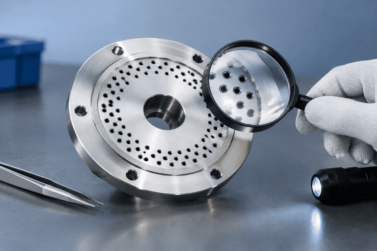
An OVD burner faceplate replacement is rarely just a parts swap. The faceplate—the front plate of the burner head, drilled with the small orifices that shape the gas streams feeding the deposition flame—sets the geometry that determines how precursor and fuel gases leave the torch. Once those holes erode, distort, or clog, the soot stream that builds the preform changes, often gradually enough that the drift is blamed on process parameters rather than hardware. This article covers what to inspect, how to judge whether a faceplate needs replacement, and what information to prepare when sourcing a new one. Because the faceplate is the final mechanical interface between gas delivery and the flame, treating an OVD burner faceplate replacement as a routine consumable change rather than a controlled engineering event is a common and costly mistake.
What the Faceplate Actually Does
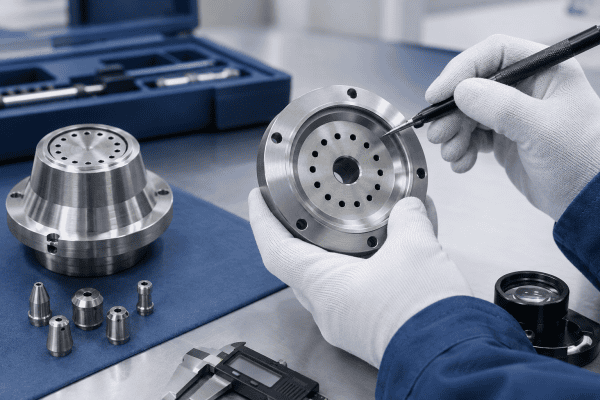
In an outside vapor deposition (OVD) process, the burner directs a flame across a rotating target rod. Multiple gas channels—typically fuel, oxygen, and a carrier gas laden with precursor vapor—exit through a faceplate and must remain stable and positioned correctly relative to one another. The faceplate is the last mechanical element that touches those streams before combustion and deposition.
That makes faceplate hole geometry a first-order process variable. Hole diameter, roundness, entry and exit chamfers, hole-to-hole spacing, and angular orientation all influence local gas velocity and mixing. Small deviations across a faceplate can shift the flame profile, which in turn affects deposition efficiency and the uniformity of the growing soot body.
It also means the faceplate is a wear part whose condition should be tracked like any other process input. When teams plan an OVD burner faceplate replacement, they are really restoring a set of geometric boundary conditions: the exit area of each orifice, the standoff from the target, and the orientation of the gas streams relative to one another. Restoring those conditions consistently is what separates a controlled replacement from a trial-and-error parts change.
Why Hole Geometry Drifts Over Time
Thermal cycling and creep
Burner faceplates operate in a high-temperature environment with repeated heating and cooling across run cycles. Depending on the material and design, this can produce gradual dimensional creep, warping, or small changes in hole profile. A faceplate that was flat when new may develop enough distortion to change the standoff between the burner and the target.
Thermal effects rarely act in isolation. A plate that was marginally flat when installed can become visibly warped after enough cycles, and the resulting standoff change alters how the flame interacts with the target surface. This is one reason an OVD burner faceplate replacement interval tied only to hours of service can miss early geometry drift that is already affecting deposition.
Oxidation and material loss
Some faceplate materials oxidize or erode at operating temperature. Material loss at the hole edge enlarges or distorts orifices, and because the effect is not uniform across the plate, the pattern of gas outlets loses the symmetry it had when new. The right material for a given faceplate depends on its function, its temperature exposure, its chemical environment, and the engineering requirements of the torch design—not simply on the general category of the part.
Material choice therefore becomes a design decision with a direct bearing on how long a faceplate holds its geometry. Where an OVD burner faceplate replacement is being planned, comparing the original material against the actual service environment is a reasonable part of the specification review.
Soot accumulation and clogging
Silica soot and reaction byproducts can build up on or inside the faceplate holes. Partial blockages change the effective orifice area, which changes flow distribution without any change in supplied gas settings. This is one of the most common reasons a burner begins to behave differently while the incoming gas parameters appear unchanged. Practical guidance on this failure mode is covered in the article on OVD and VAD burner maintenance and lifespan extension.
Inspection: What to Check and How to Verify It
Inspection should separate observed symptoms from confirmed causes. A faceplate is only one possible explanation for a process shift, and it should not be replaced on suspicion alone when other causes remain unruled out.
A useful inspection sequence moves from the process outward to the part: first document the symptom, then narrow the possible causes, and only then disassemble the torch for a direct look at the faceplate. An OVD burner faceplate replacement decision is much easier to defend when it rests on that kind of evidence rather than on a hunch.
Start with the deposition symptom
Record what actually changed: soot deposition rate, preform diameter uniformity, flame appearance, or refractive index profile. These symptoms narrow the search. A slow decline in deposition rate may point to faceplate wear or clogging, but it can also relate to gas supply, torch standoff, or target rotation. The relationship between declining deposition rate and burner condition is discussed in the article on why OVD burner flames tilt.
Refractive index profile drift is another symptom that often traces back to geometry rather than to gas settings. When concentricity or stream alignment shifts, the deposited layers can lose the symmetry the process depends on. That failure path is examined in the article on refractive index profile drift in OVD burners. If profile drift and a slow deposition decline appear together, a faceplate inspection belongs near the top of the diagnostic list.
Visual and dimensional checks
With the burner removed and cooled per site procedures:
- Hole-by-hole comparis—inspect each orifice against a known-good reference or the original drawing. Look for enlargement, ovality, burrs, or rounded edges that no longer match the specified profile.
- Flatness and warpage—check the faceplate surface against a reference plane. Localized distortion changes the effective standoff between holes and the deposition surface.
- Clogging and deposits—examine holes under magnification and with backlighting where practical. Deposits may be visible at the entry, exit, or within the bore.
- Hole pattern symmetry—verify hole-to-hole spacing and alignment with the gas channel layout behind the plate. Pattern drift is easier to see by comparison than by absolute measurement.
- Sealing surfaces—check mating faces, gasket seats, and any locating features for wear, scoring, or distortion that could cause leakage or misalignment.
For dimensional measurement practices, the general guidance published by NIST on dimensional metrology is a useful reference for calibration and measurement uncertainty, which matters when the tolerance being judged is measured in micrometers.
Confirming whether the faceplate is the cause
Where the process allows, the most reliable verification is substitution with a known-good faceplate, followed by a controlled run and comparison against baseline data. This converts a suspicion into evidence before committing to replacement. If symptoms persist after substitution, the faceplate was not the root cause, and attention should shift to gas delivery, torch position, or other components.
Timing matters here as well. If substitution restores baseline deposition, the case for a permanent OVD burner faceplate replacement is straightforward. If it does not, the investigation continues without spending a replacement cycle on the wrong component.
Deciding Between Cleaning, Reconditioning, and Replacement
Not every contaminated faceplate needs replacement. Surface deposits that can be removed without altering hole geometry may be addressed through the cleaning procedure specified by the equipment documentation and approved by qualified personnel. Follow manufacturer guidance and your site’s safety rules for any cleaning operation—this article does not prescribe chemical or mechanical cleaning methods.
Replacement is the more appropriate path when:
- Hole geometry has measurably changed—enlargement, ovality, or profile deviation beyond the drawing tolerance.
- The faceplate is warped or distorted beyond acceptable flatness.
- Deposits have bonded or penetrated in a way that cannot be removed without damaging the orifice.
- Cleaning has already been attempted and the process symptom returns.
- Sealing or locating features are worn enough to affect alignment.
Where dimensional evidence is ambiguous, a dimensional report from a qualified inspection source is more useful than a judgment call at the machine. An OVD burner faceplate replacement performed on ambiguous evidence tends to be repeated sooner than one backed by measurement.
What Matters in a Replacement Faceplate
The quality of an OVD burner faceplate replacement depends less on how the part is ordered than on how completely its geometry is specified. Three areas deserve attention before a purchase order is raised: the hole pattern, the material, and the interfaces that seat and seal the plate.
Hole geometry is the specification
The defining requirement of a replacement is that the hole pattern matches the original drawing—diameter, tolerance, spacing, orientation, and edge condition. A faceplate that fits mechanically but differs in hole geometry is not an equivalent replacement. This is why drawing-based production and dimensional verification matter more here than broad dimensional similarity. Precision in nozzle and orifice features has a direct relationship to preform outcomes, as explored in the article on custom OVD burner nozzle replacement.
It also explains why a faceplate should not be accepted on the basis of a visual match alone. Two plates can look identical and still differ in one chamfer angle or spacing dimension that governs local mixing. When an OVD burner faceplate replacement is specified, the drawing is the acceptance criterion, not the appearance of the part.
Material selection
Faceplate material should be selected against the actual service conditions: peak temperature, thermal cycling, exposure to process gases and reaction products, and mechanical requirements. Two burners with the same external dimensions may legitimately use different faceplate materials. Treat any recommendation as conditional on the specific application rather than as a general rule.
Material also interacts with replacement frequency. A plate that resists oxidation and retains flatness longer will extend the interval between services, which is often worth more than a marginal reduction in part cost. For context on how alloy choices have performed in demanding service, the case study on titanium OVD burner parts for a tier-one fiber manufacturer reviews one such upgrade.
Fit, alignment, and gas connections
Mounting features, locating pins, gasket interfaces, and gas inlet geometry all affect how the faceplate seats and seals. A replacement should be checked against the burner body drawing, not just the faceplate outline. Gas connection details are frequently where substitution goes wrong, and they are examined in the article on OVD burner head replacement and gas connections.
Alignment features deserve the same scrutiny. A locating pin that no longer seats cleanly can rotate the plate slightly relative to the torch body, which shifts the entire stream pattern even though every individual hole is within tolerance. That is why an OVD burner faceplate replacement should include verification of how the plate registers against the body, not only how the holes measure on the bench.
Common Mistakes During Faceplate Replacement
Most failed replacements share a small number of causes. Reviewing them before the job starts is cheaper than repeating the work.
- Replacing on symptom alone. A process shift without dimensional evidence may point somewhere other than the faceplate.
- Accepting mechanical fit as equivalence. A plate that bolts up correctly can still have the wrong hole pattern.
- Skipping the post-change baseline. Without a controlled run against baseline data, there is no way to confirm the replacement actually resolved the issue.
- Mixing parts across processes. OVD, VAD, and MCVD burners differ in design and operating conditions and components are not interchangeable without engineering review.
- Reusing worn sealing hardware. Gaskets and sealing faces that were acceptable on the old plate may not seal correctly on a new one.
Each of these mistakes turns a single OVD burner faceplate replacement into a sequence of replacements, and each one is avoidable with a short checklist and a drawing on the bench.
Preparing a Sourcing Request
A clear request shortens the path to a usable part. Include:
- The faceplate drawing, including hole pattern, tolerances, and edge specifications.
- Material specification and any surface or hardness requirements.
- Photos of the existing part, including any wear or damage.
- Burner model or torch assembly identification, with the caveat that compatibility must be verified against drawings rather than assumed from a model name.
- Operating conditions relevant to material selection—temperature range, gas environment, and cycling pattern.
- Quantity and any inspection documentation required.
Where drawings are unavailable or incomplete, reverse engineering from a physical sample is a practical route. Custom faceplates and other non-standard components can be produced through OEM and ODM machining services based on supplied drawings, dimensions, and material requirements.
For standard replacement options across burner and torch assemblies, the OVD torch spare parts range includes burner heads, nozzle components, and related consumables, and specific configurations are listed under OVD auxiliary tail burner and oxygen distribution manifold. Note that OVD, VAD, and MCVD burners differ in design and operating conditions; components are not interchangeable across these processes without engineering review.
Frequently Asked Questions
How often should an OVD burner faceplate be inspected?
Inspection frequency depends on duty cycle, process sensitivity, and how quickly the burner environment degrades the faceplate. Rather than a fixed interval, tie inspection to process monitoring: when deposition rate, flame stability, or profile uniformity drifts beyond your control limits, add a faceplate inspection to the diagnostic sequence.
Can a clogged faceplate be cleaned instead of replaced?
Sometimes, if the deposit is surface-level and can be removed without changing hole geometry. If cleaning alters the orifice edge, enlarges the hole, or if the symptom returns quickly, replacement is the more reliable option. Cleaning methods should follow equipment documentation and qualified personnel guidance.
What is the most important dimension to check on a replacement faceplate?
Hole geometry—diameter, tolerance, spacing, and edge condition—because it directly governs gas distribution. Flatness and mounting alignment come next, since they affect seating and standoff. Mechanical fit alone does not confirm a faceplate is equivalent.
Can a faceplate from one burner model be used on another?
Not without verification. Compatibility must be confirmed against drawings, dimensions, gas connections, materials, and application requirements. Model names alone are not sufficient evidence of interchangeability.
What documentation should accompany an OVD burner faceplate replacement?
At minimum, a dimensional report covering hole geometry and flatness, plus material certification where the application requires it. Records of the pre-change symptom and the post-change baseline run are equally useful, because they establish whether the replacement achieved its purpose and give the next inspection a reference point.
Next Step
If you are evaluating an OVD burner faceplate replacement, the fastest route to a correct part is a complete data package. Send the faceplate drawing, material requirements, photos of the current part, and the relevant operating conditions to request a quotation. Where drawings are missing or incomplete, note that in your inquiry so the reverse engineering route can be assessed alongside standard replacement options. A complete package also makes it easier to confirm that the replacement you receive matches the geometry your process was built around, which is ultimately the point of planning an OVD burner faceplate replacement carefully in the first place.
