
지식
광섬유 권취기 클램프 교체: 권취기 클램프 교체: 치수 및 그립 점검
10월
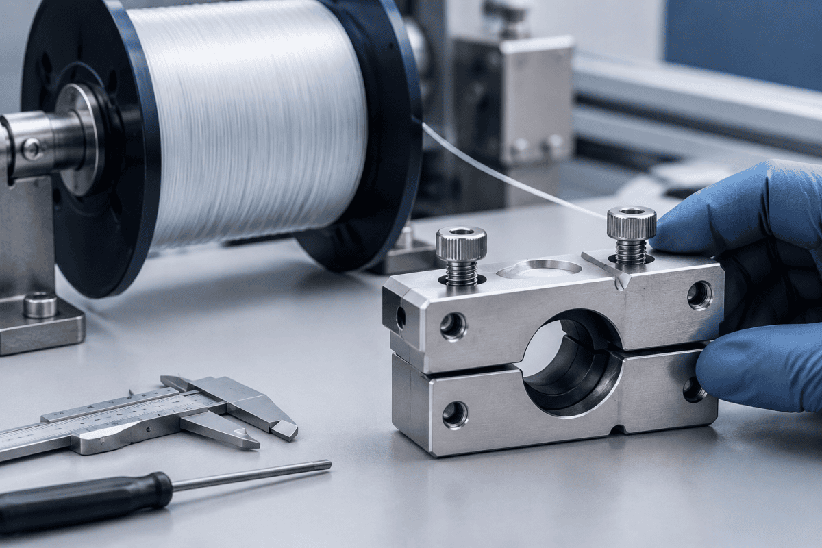
광섬유 권취기 클램프 교체는 단순히 “마모된 부품을 교체하는” 작업인 경우가 거의 없습니다. 클램프는 권취 중 광섬유를 제어된 장력으로 유지하므로, 치수나 그립 동작의 변화가 권취 품질, 보빈 체인지오버 신뢰성, 광섬유 핸들링 손실에 직접 영향을 미칠 수 있습니다. 부품을 소싱하든 광섬유 와인더 클램프 및 커터 어셈블리 맞춤형 교체품을 평가하든, 성공을 결정하는 두 가지 요소는 치수 적합성과 그립 일관성입니다. 이 글에서는 측정해야 할 항목, 검사해야 할 항목, 그리고 권취 스테이션에서 실제로 작동하는 교체품을 견적하기 위해 공급업체에 필요한 정보를 설명합니다.
광섬유 권취기 클램프 교체가 중요한 이유
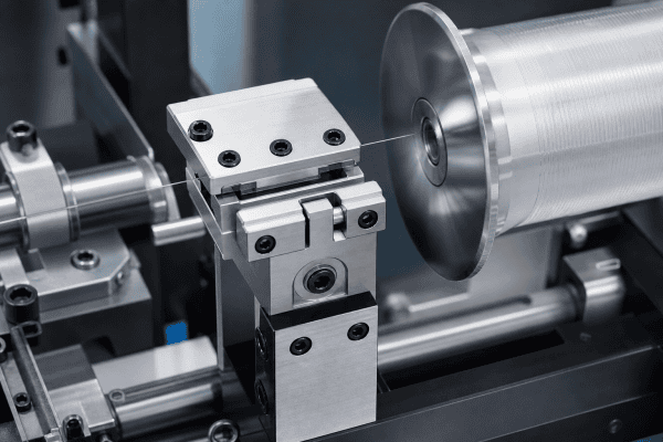
권취기는 광섬유 인출 공정과 스풀 사이의 최종 기계적 인터페이스입니다. 광섬유가 도착하면 클램프와 관련 커터 어셈블리가 각 권취 사이클 또는 보빈 체인지오버의 시작과 끝에서 광섬유를 잡고, 자르고, 이송합니다. 이는 지속적인 움직임, 노출된 유리 광섬유와의 접촉, 수천 번의 반복 사이클이라는 까다로운 환경에서 작동합니다.
클램프가 마모되거나 그립이 저하되면 여러 가지 방식으로 그 결과가 나타납니다:
- 권취 중 광섬유 슬립 으로 인해 느슨하거나 불균일한 감김을 유발할 수 있습니다.
- 권취 시작 불량 이송 지점에서 광섬유가 깨끗하게 포착되지 않는 경우.
- 광섬유 손상 또는 파손 그립부에서, 특히 버, 날카로운 모서리, 과도한 클램핑력으로 인해 발생합니다.
- 조기 절단 또는 빠짐 그립이 너무 약하거나 커터 타이밍이 맞지 않는 경우.
- 수율 손실 및 다운타임 반복적인 체인지오버 조정으로 인해 발생합니다.
클램프를 과도하게 조이는 것은 해결책이 아니며, 슬립을 정상으로 받아들이는 것도 해결책이 아닙니다. 둘 다 클램프 형상이나 표면 상태가 더 이상 설계 요구 사항과 일치하지 않음을 나타내므로, 교체 결정은 감각이 아닌 측정을 기반으로 해야 합니다.
교체품 주문 전 확인해야 할 치수
권취기 클램프는 적합성이 중요한 부품입니다. 작은 불일치만으로도 커터 어셈블리와의 정렬 불량, 일관되지 않은 그립 압력, 권취 경로와의 간섭이 발생할 수 있습니다. 교체를 요청하기 전에 장비 문서에서 또는 정상 작동하는 부품을 측정하여 다음 치수를 확인하십시오.
장착 인터페이스
볼트 구멍 간격, 나사 크기 및 피치, 다웰 또는 위치 결정 핀의 위치를 확인하십시오. 클램프는 심을 사용하지 않고 장착면에 안착해야 합니다. 심을 사용하면 그립 포인트와 커터 사이의 관계가 변경되기 때문입니다. 원래 장착 패턴이 문서화되지 않은 경우, 실물 샘플이나 도면을 기반으로 한 맞춤형 광섬유 장비 부품 접근 방식이 육안으로 맞추는 것보다 일반적으로 더 신뢰할 수 있습니다.
그립 포인트 형상
그립 표면은 — 평평한 패드, V홈, 또는 프로파일 조 중 어느 것이든 — 광섬유 라우팅과 일치해야 합니다. 다음을 기록하십시오:
- 장착면에서 그립 중심선까지의 거리.
- 그립 홈 또는 패드의 너비와 깊이.
- 조 개구 범위 및 닫힘 위치.
그립 포인트가 광섬유 경로에서 1밀리미터의 일부라도 벗어나면, 클램프가 체인지오버 중에 광섬유를 측면으로 당길 수 있으며, 이는 보빈의 첫 번째 감김에 영향을 미칠 수 있습니다.
커터 어셈블리 정렬
클램프와 커터는 종종 한 쌍으로 작동하므로, 둘 사이의 상대적 위치가 개별 치수만큼 중요합니다. 절단면 위치, 클램프와 커터 블레이드 사이의 간극, 작동 스트로크를 기록하십시오. 자체적으로 치수가 정확한 교체 클램프라도 블레이드에 대한 광섬유 위치를 이동시키면 절단 불량을 유발할 수 있습니다.
작동 인터페이스
클램프가 어떻게 작동되는지 — 공압, 기계식 링키지, 또는 수동 — 와 관련된 스트로크, 보어, 또는 링키지 형상을 기록하십시오. 교체품이 유효 스트로크를 변경하면 외부 치수가 일치하더라도 그립력과 타이밍이 변경됩니다.
그립 점검: 광섬유 접촉면에서 검사해야 할 사항
치수 적합성은 클램프를 기계에 장착시킵니다. 그립 상태는 작동 여부를 결정합니다. 광섬유는 취약한 유리 필라멘트이므로 접촉면은 자국, 압착, 또는 긁힘 없이 광섬유를 잡아야 합니다.
분리된 클램프와 설치 전 교체품에서 다음을 검사하십시오:
- 표면 조도. 그립 패드 또는 조 면은 매끄럽고 버, 가공 자국, 또는 박힌 이물질이 없어야 합니다. 확대하여 광섬유에 흠집을 낼 수 있는 돌출된 모서리가 있는지 확인하십시오.
- 마모 패턴. 불균일하게 마모된 클램프 — 한쪽은 연마되고 다른 쪽은 여전히 거친 경우, 또는 한 패드에 홈이 마모된 경우 — 는 정렬 불량 또는 편심 하중을 나타냅니다. 정렬을 교정하지 않고 클램프를 교체하면 마모가 재발합니다.
- 그립 패드 상태. If the clamp uses elastomer or polymer pads, check for hardening, compression set, or contamination. Material selection depends on the fiber coating, contact pressure, and cycle rate, so pad replacement should follow the original engineering requirement rather than a generic substitute.
- Contamination. Glass dust, coating residue, or lubricant on the grip surface will reduce friction and cause slippage. Clean according to your equipment documentation and verify that cleaning does not alter the surface.
그립력 확인
Grip force should be verified against the equipment specification, not adjusted by trial and error during production. If your station provides a way to measure clamping force or actuation pressure, compare the reading with the documented value. If it does not, check the actuation linkage and pneumatic circuit for wear or leakage before concluding that the clamp itself is the problem. A clamp is one part of a system; weak grip can originate upstream in the actuator.
일반적인 고장 모드 및 확인 방법
Distinguishing a worn clamp from a related fault saves unnecessary replacement cost. The table below separates possible causes from the checks that confirm them.
- Fiber slippage at start of wind. Possible causes: worn grip pads, contaminated grip surface, low actuation pressure, or misaligned clamp. Confirmation: clean and re-test; measure clamping force; check clamp position against the fiber path.
- Fiber damage or nicks at the grip. Possible causes: burrs or sharp edges on the jaw, excessive grip force, or foreign particles embedded in the pad. Confirmation: inspect under magnification; verify force setting; replace damaged pads.
- Poor cut quality at changeover. Possible causes: clamp-to-cutter misalignment, worn cutter blade, or changed clamp stroke. Confirmation: check the cutting plane location and blade condition; verify the clamp is fully seated at the cut position.
- Inconsistent winding tension. Possible causes: slipping clamp, worn pad, or erratic actuation. Confirmation: log tension data across cycles and correlate with changeover events; inspect the actuator before replacing the clamp.
- Repeat failures on the same station. Possible causes: mounting surface damage, bent linkage, or incorrect replacement part. Confirmation: compare dimensions with a known-good station; check the mounting interface for wear.
In each case, the clamp is a candidate — but not the only one. Replacing a clamp to fix an actuator or alignment problem usually produces the same failure again within a short time.
맞춤형 권취기 클램프가 적합한 경우
Standard replacement parts work well when the original design is documented and the equipment is unmodified. Custom manufacturing becomes the practical option when:
- The original clamp or cutter assembly is obsolete or no longer supported.
- You have a physical sample but no current drawing.
- Your process requires a different grip profile, pad material, or stroke to suit a specific fiber type or winding recipe.
- You want to consolidate a worn multi-part assembly into a single replacement unit with verified geometry.
For these cases, reverse engineering from a sample or a marked-up drawing allows the supplier to reproduce the mounting interface and grip geometry while confirming the fiber contact surface. Material selection should follow the component’s function: the structural body, the actuation interface, and the fiber contact pad each have different requirements, and the choice depends on load, wear exposure, and the fiber coating involved. The same principle applies across preform and draw equipment, as discussed in the guide to Nextrom VAD burner replacement parts.
명확한 소싱 요청서 준비
A well-prepared request shortens the quotation cycle and reduces the risk of a part that fits on paper but not in the machine. Include the following:
- Drawings or a sample. A dimensioned drawing is ideal. If unavailable, a clean sample with critical dimensions marked is the next best option.
- Critical dimensions. Identify which dimensions are functional — mounting pattern, grip centerline, cutter clearance — and which are nominal.
- Material and surface requirements. State the requirements for the body, the grip surface, and any pad or insert. Note whether the fiber contacts metal, polymer, or a coated surface.
- Operating conditions. Cycle rate, actuation type, fiber type and coating, and cleaning method. These influence material and finish selection.
- Quantity and application. Note whether this is a one-off replacement, a spare parts program, or a redesign.
Photographs of the installed assembly, including the mounting interface and the cutter relationship, are often as useful as the drawing itself.
교체 클램프 평가를 위한 실용적 단계
Before you commit to a replacement, run through a structured evaluation. Start with a dimensional audit of the removed part using calibrated instruments. Record every relevant dimension, including those that are not obviously critical, and compare them to the original specification. If the original specification is missing, measure multiple samples to establish a baseline. Next, assess the grip interface under magnification. A surface that appears smooth to the naked eye may reveal micro-burrs or embedded particles under 10x or 20x magnification. These defects can damage fiber even if the clamp holds tension correctly. Finally, verify the actuation stroke and force. Use a force gauge or pressure sensor to confirm that the clamp delivers the specified grip. If the force is out of range, investigate the actuator and linkage before replacing the clamp.
For engineers working with obsolete equipment, the optical fiber take up winder clamp replacement process often requires reverse engineering. A supplier with experience in fiber draw tower components can produce a replacement that matches the original geometry and material specifications. The key is to provide clear documentation of the mounting interface, grip geometry, and actuation requirements. Without these details, even a well-machined part may not perform as expected.
중요 치수 측정 및 문서화 방법
Accurate measurement is the foundation of a successful optical fiber take up winder clamp replacement. Use the following steps to document the critical dimensions of your original clamp. First, clean the part thoroughly to remove any fiber dust or lubricant. Next, use a coordinate measuring machine (CMM) or precision calipers to record the mounting hole pattern, including hole diameter and center-to-center distances. For the grip point, measure the distance from the mounting face to the center of the grip groove or pad. If the clamp has a V-groove, measure the groove angle and depth. For the actuation interface, measure the stroke length and the diameter of any pneumatic or mechanical connection. Document all measurements in a table or drawing. Include photographs of the part from multiple angles, and note any wear or damage. This documentation will help your supplier understand the requirements and reduce the risk of a misfit.
When you request a quote, ask the supplier to confirm that they can achieve the required tolerances. For grip-critical dimensions, tolerances of ±0.01 mm may be necessary. For mounting holes, ±0.05 mm is often sufficient. Discuss the material and surface finish requirements as well. The clamp body is typically machined from aluminum or stainless steel, while the grip pad may be a polymer or elastomer. The surface finish on the grip should be smooth but not polished to a mirror finish, as some texture can improve grip without damaging the fiber. Your supplier should be able to recommend the best material and finish based on your operating conditions.
광섬유 접촉부의 재질 및 표면 처리
The material of the clamp and its grip surface directly affect fiber handling. For the clamp body, aluminum alloys are common due to their light weight and machinability. Stainless steel offers greater durability and corrosion resistance, which is important in humid environments or when cleaning agents are used. The grip pad material must balance friction, wear resistance, and compatibility with the fiber coating. Polyurethane and silicone are frequently used because they provide good grip without marking the fiber. However, the choice depends on the fiber coating: acrylate coatings may require a different pad material than polyimide coatings. Surface treatments such as anodizing or hard coating can improve wear resistance on aluminum parts. For stainless steel, passivation helps prevent corrosion. In all cases, the surface that contacts the fiber must be free of burrs and sharp edges. A deburring and polishing step is essential after machining. Some suppliers offer electropolishing for stainless steel parts, which creates a smooth, uniform surface that reduces the risk of fiber damage.
When specifying a custom replacement, provide the original material specification if available. If not, describe the operating environment and the fiber type. Your supplier can then recommend a suitable material. For high-cycle applications, consider a hardened grip insert or a replaceable pad. This can extend the life of the clamp and simplify maintenance. Remember that the optical fiber take up winder clamp replacement should be a drop-in fit. Any change in material or surface finish can affect the grip characteristics, so it is important to validate the replacement under production conditions before full-scale use.
설치 및 정렬 모범 사례
Proper installation ensures that the optical fiber take up winder clamp replacement performs as intended. Before installing the new clamp, inspect the mounting surface for damage or wear. Clean the surface and remove any old gaskets or shims. If the mounting surface is damaged, repair or replace it before installing the clamp. Align the clamp using dowel pins or locating features if present. Tighten the mounting bolts in a star pattern to avoid distorting the clamp body. After installation, check the clearance between the clamp and the cutter assembly. Use a feeler gauge to verify the specified clearance. Next, cycle the clamp several times without fiber to check for smooth operation and proper stroke. If the clamp is pneumatically actuated, check for air leaks and verify the pressure setting. Finally, run a test with fiber and inspect the first few wraps for signs of slippage or damage. Adjust the clamp force or alignment if necessary. Document the installation and any adjustments for future reference.
Regular maintenance can extend the life of the clamp and prevent unexpected failures. Establish a schedule for inspecting grip pads, cleaning the grip surface, and checking actuation force. Keep spare pads or clamps on hand for critical stations. By following these practices, you can minimize downtime and maintain consistent winding quality. The effort spent on a careful optical fiber take up winder clamp replacement will pay off in reduced fiber waste and improved productivity.
자주 묻는 질문
클램프 전체 대신 그립 패드만 교체할 수 있습니까?
It depends on how the pad is retained and whether the clamp body is still within its dimensional limits. If the body is worn, bent, or its grip geometry has changed, replacing only the pad will not restore performance. Inspect the body first, then decide.
클램프 또는 커터 중 어느 것이 체인지오버 문제를 일으키는지 어떻게 알 수 있습니까?
Separate the functions: check whether the fiber is held securely before the cut, and whether the cut occurs at the correct position. If grip is lost before cutting, the clamp or its actuation is the likely source. If grip holds but the cut is poor, check cutter condition and clamp-to-cutter alignment.
맞춤형 클램프가 제 권취기 모델과 호환됩니까?
Compatibility must be verified against your drawings, dimensions, mounting interface, actuation type, and application requirements. A supplier cannot confirm fit for a specific machine model without those details. Provide the sample or drawing and let the dimensions drive the answer.
교체 요청에서 가장 자주 누락되는 정보는 무엇입니까?
The relationship between the clamp and the cutter assembly is the most common gap. Supplying the clamp dimensions alone is not enough if the cutter clearance and cutting plane are not defined.
다음 단계
If you are facing an obsolete clamp, a worn cutter assembly, or a winding station that will not hold tension consistently, gather the drawing or sample, mark the critical dimensions, and note the actuation and fiber contact requirements. You can contact our team to discuss your component requirements and request a quotation based on your drawings, dimensions, materials, and operating conditions. For related take-up and handling components, you can also browse the optical fiber equipment parts range to see how replacement components are organized by function. For additional technical details on fiber handling and component specifications, refer to the Corning Optical Communications resource library, which offers reputable guidance on fiber handling and equipment maintenance. A well-executed optical fiber take up winder clamp replacement ensures reliable winding, reduces fiber waste, and keeps your draw tower operating at peak efficiency.
권취기 클램프 어셈블리 이해
The take-up winder clamp assembly is a critical component in optical fiber drawing towers. It is responsible for gripping the fiber at the start and end of each winding cycle, transferring it to the bobbin, and maintaining consistent tension. The clamp works in conjunction with a cutter assembly, which cuts the fiber at the appropriate point during bobbin changeover. Together, these components ensure that the fiber is wound without slippage, damage, or tension variations. In high-speed drawing operations, the clamp must cycle thousands of times per day. Over time, the grip surfaces wear, the actuation mechanism may degrade, and the clamp may lose its ability to hold the fiber securely. Regular inspection and timely replacement are essential to prevent quality issues and downtime.
When the clamp begins to fail, the symptoms may be subtle at first. You might notice occasional slippage at the start of a wind, or a slight variation in tension that causes loose wraps. As wear progresses, the problems become more frequent and severe, leading to fiber breaks or complete production stoppages. The key is to identify the early signs and address them before they escalate. This is where a thorough optical fiber take up winder clamp replacement becomes necessary. By understanding the function of the clamp and the factors that contribute to its wear, you can make informed decisions about replacement and maintenance.
클램프 교체가 필요한 징후
Recognizing the signs of a worn clamp is the first step toward a successful replacement. Common indicators include visible wear on the grip pads, such as grooves, flat spots, or embedded debris. The clamp may also show signs of corrosion or pitting if it is not properly maintained. In pneumatic clamps, leaks or inconsistent actuation can indicate internal wear. From an operational standpoint, increased fiber slippage, inconsistent tension, or poor cut quality at changeover are strong signals. If you notice that the clamp requires frequent adjustment to maintain grip, it is likely beyond its useful life. Another sign is a change in the sound of the clamp during operation — a sluggish or irregular actuation may indicate mechanical wear. Collecting data on these symptoms can help you pinpoint the issue and justify a replacement.
Once you have identified the need for replacement, the next step is to gather the necessary information for sourcing. This includes the original part number, drawings, and any specifications you have. If these are unavailable, a sample of the worn part can serve as a reference. Photograph the part from multiple angles and measure critical dimensions. Document the operating conditions and the fiber type. With this information, you can approach suppliers and request quotes for a replacement or a custom-manufactured part. The goal is to obtain a clamp that matches the original in form, fit, and function, ensuring a smooth transition and minimal downtime.
