
Знание
Замена зажима приемно-намоточного устройства для оптического волокна: Замена зажима приемно-намоточного устройства: Размеры и проверка захвата
Окт
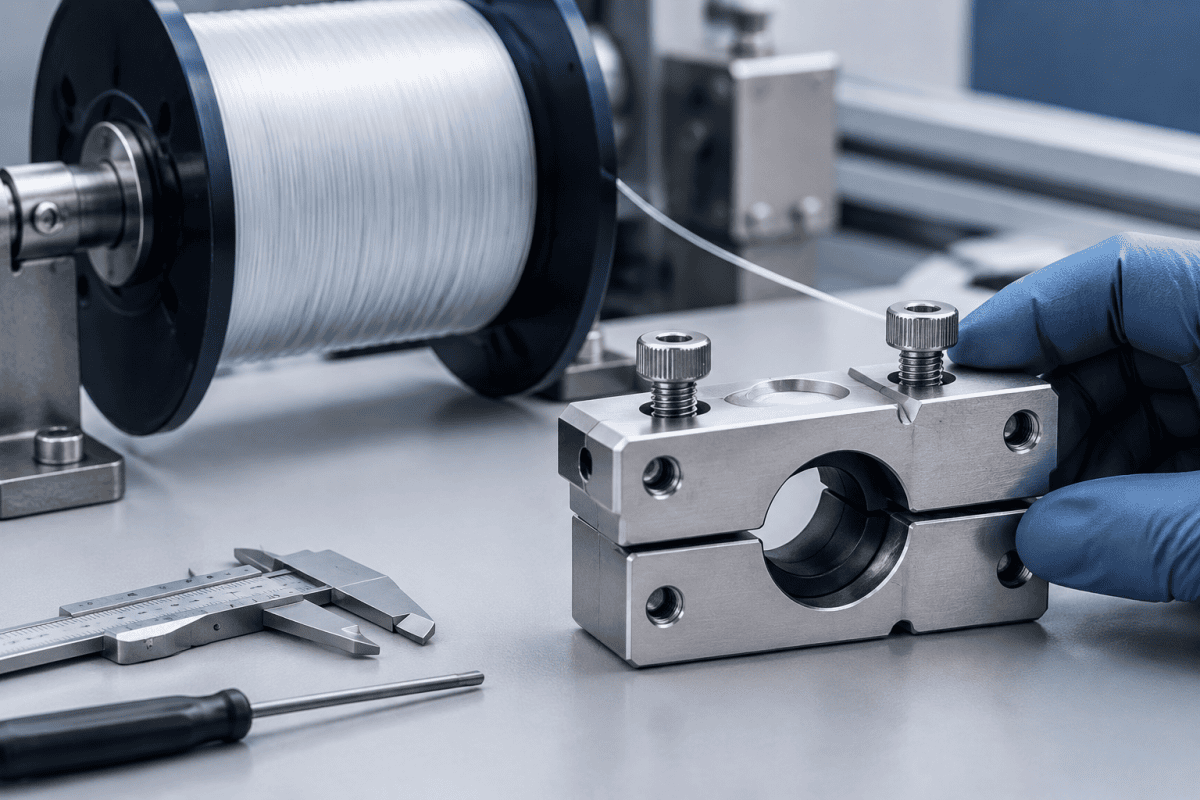
Замена зажима намоточного устройства для оптического волокна редко является простой задачей “заменить изношенную деталь”. Зажим удерживает волокно под контролируемым натяжением во время намотки, поэтому любое отклонение в его размерах или поведении захвата может напрямую отразиться на качестве намотки, надёжности смены катушек и потерях при обращении с волокном. Независимо от того, закупаете ли вы зажима намотчика оптического волокна и режущего узла компоненты или оцениваете замену по индивидуальному заказу, два фактора определяют успех: размерное соответствие и стабильность захвата. В этой статье объясняется, что измерять, что осматривать и что нужно поставщику для расчёта стоимости замены, которая действительно будет работать на вашей приёмной станции.
Почему замена зажима намоточного устройства для оптического волокна имеет значение
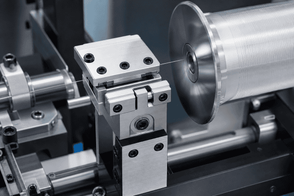
Приёмное намоточное устройство — это конечный механический интерфейс между процессом вытяжки волокна и катушкой. Когда волокно поступает, зажим и связанный с ним узел резака захватывают, разрезают и передают волокно в начале и конце каждого цикла намотки или смены катушки. Он работает в тяжёлых условиях: непрерывное движение, контакт с оголённым стеклянным волокном и повторяющиеся циклы тысячи раз.
Когда зажим изнашивается или его захват ухудшается, последствия проявляются несколькими способами:
- Проскальзывание волокна во время намотки, что может вызвать слабые или неравномерные витки.
- Дефекты начала намотки если волокно не захватывается чисто в точке передачи.
- Повреждение или обрыв волокна в месте захвата, особенно из-за заусенцев, острых кромок или чрезмерного усилия зажима.
- Преждевременная резка или выдёргивание если захват слишком слабый или неправильно настроена синхронизация резака.
- Потеря выхода годной продукции и простои из-за повторяющихся регулировок при переналадке.
Чрезмерная затяжка зажима не является решением, как и принятие проскальзывания как нормы. Оба признака указывают на то, что геометрия зажима или состояние поверхности больше не соответствуют проектным требованиям, поэтому решения о замене должны основываться на измерениях, а не на ощущениях.
Размеры для проверки перед заказом замены
Зажим намоточного устройства — это компонент, критичный к посадке. Даже небольшие несоответствия могут вызвать смещение относительно узла резака, непостоянное давление захвата или помехи на пути намотки. Перед запросом на замену подтвердите следующие размеры по документации на оборудование или путём измерения заведомо исправной детали.
Монтажный интерфейс
Проверьте расстояние между отверстиями под болты, размер и шаг резьбы, а также положение штифтов или установочных пальцев. Зажим должен прилегать к своей монтажной поверхности без прокладок, поскольку прокладки изменяют взаимосвязь между точкой захвата и резаком. Если исходная схема монтажа не задокументирована, подход с изготовлением деталей для оптического оборудования по индивидуальному заказу на основе физического образца или чертежа обычно надёжнее, чем подбор на глаз.
Геометрия точки захвата
Поверхность захвата — будь то плоская накладка, V-образный паз или профилированная губка — должна соответствовать траектории волокна. Зафиксируйте:
- Расстояние от монтажной поверхности до осевой линии захвата.
- Ширину и глубину паза или накладки захвата.
- Диапазон раскрытия губок и закрытое положение.
Если точка захвата смещена от траектории волокна хотя бы на долю миллиметра, зажим может тянуть волокно в сторону во время переналадки, что может повлиять на первые витки на катушке.
Выравнивание узла резака
Поскольку зажим и резак часто работают как согласованная пара, относительное положение между ними имеет такое же значение, как и их отдельные размеры. Отметьте расположение плоскости резания, зазор между зажимом и лезвием резака, а также ход привода. Зажим на замену, размерно правильный сам по себе, всё равно может вызывать плохие резы, если он смещает положение волокна относительно лезвия.
Интерфейс привода
Зафиксируйте, как приводится в действие зажим — пневматически, механическим рычагом или вручную — и соответствующий ход, диаметр отверстия или геометрию рычага. Если замена изменяет эффективный ход, усилие захвата и синхронизация изменятся, даже если внешние размеры совпадают.
Проверки захвата: что осматривать на контактной поверхности с волокном
Размерное соответствие обеспечивает установку зажима в машину. Состояние захвата определяет, работает ли он. Оптическое волокно — это хрупкая стеклянная нить, поэтому контактная поверхность должна удерживать без следов, раздавливания или царапин.
Осмотрите следующее на снятом зажиме и на любой замене перед установкой:
- Чистота поверхности. Захватные накладки или поверхности губок должны быть гладкими и свободными от заусенцев, следов обработки или встроенных загрязнений. Под увеличением ищите любую выступающую кромку, которая может поцарапать волокно.
- Характер износа. Зажим, изношенный неравномерно — одна сторона отполирована, другая всё ещё шероховата, или в одну накладку втёрт паз — указывает на смещение или внецентренную нагрузку. Замена зажима без устранения смещения воспроизведёт износ.
- Grip pad condition. If the clamp uses elastomer or polymer pads, check for hardening, compression set, or contamination. Material selection depends on the fiber coating, contact pressure, and cycle rate, so pad replacement should follow the original engineering requirement rather than a generic substitute.
- Contamination. Glass dust, coating residue, or lubricant on the grip surface will reduce friction and cause slippage. Clean according to your equipment documentation and verify that cleaning does not alter the surface.
Проверка усилия захвата
Grip force should be verified against the equipment specification, not adjusted by trial and error during production. If your station provides a way to measure clamping force or actuation pressure, compare the reading with the documented value. If it does not, check the actuation linkage and pneumatic circuit for wear or leakage before concluding that the clamp itself is the problem. A clamp is one part of a system; weak grip can originate upstream in the actuator.
Типичные режимы отказов и способы их подтверждения
Distinguishing a worn clamp from a related fault saves unnecessary replacement cost. The table below separates possible causes from the checks that confirm them.
- Fiber slippage at start of wind. Possible causes: worn grip pads, contaminated grip surface, low actuation pressure, or misaligned clamp. Confirmation: clean and re-test; measure clamping force; check clamp position against the fiber path.
- Fiber damage or nicks at the grip. Possible causes: burrs or sharp edges on the jaw, excessive grip force, or foreign particles embedded in the pad. Confirmation: inspect under magnification; verify force setting; replace damaged pads.
- Poor cut quality at changeover. Possible causes: clamp-to-cutter misalignment, worn cutter blade, or changed clamp stroke. Confirmation: check the cutting plane location and blade condition; verify the clamp is fully seated at the cut position.
- Inconsistent winding tension. Possible causes: slipping clamp, worn pad, or erratic actuation. Confirmation: log tension data across cycles and correlate with changeover events; inspect the actuator before replacing the clamp.
- Repeat failures on the same station. Possible causes: mounting surface damage, bent linkage, or incorrect replacement part. Confirmation: compare dimensions with a known-good station; check the mounting interface for wear.
In each case, the clamp is a candidate — but not the only one. Replacing a clamp to fix an actuator or alignment problem usually produces the same failure again within a short time.
Когда зажим намоточного устройства по индивидуальному заказу имеет смысл
Standard replacement parts work well when the original design is documented and the equipment is unmodified. Custom manufacturing becomes the practical option when:
- The original clamp or cutter assembly is obsolete or no longer supported.
- You have a physical sample but no current drawing.
- Your process requires a different grip profile, pad material, or stroke to suit a specific fiber type or winding recipe.
- You want to consolidate a worn multi-part assembly into a single replacement unit with verified geometry.
For these cases, reverse engineering from a sample or a marked-up drawing allows the supplier to reproduce the mounting interface and grip geometry while confirming the fiber contact surface. Material selection should follow the component’s function: the structural body, the actuation interface, and the fiber contact pad each have different requirements, and the choice depends on load, wear exposure, and the fiber coating involved. The same principle applies across preform and draw equipment, as discussed in the guide to Nextrom VAD burner replacement parts.
Подготовка чёткого запроса на закупку
A well-prepared request shortens the quotation cycle and reduces the risk of a part that fits on paper but not in the machine. Include the following:
- Drawings or a sample. A dimensioned drawing is ideal. If unavailable, a clean sample with critical dimensions marked is the next best option.
- Critical dimensions. Identify which dimensions are functional — mounting pattern, grip centerline, cutter clearance — and which are nominal.
- Material and surface requirements. State the requirements for the body, the grip surface, and any pad or insert. Note whether the fiber contacts metal, polymer, or a coated surface.
- Operating conditions. Cycle rate, actuation type, fiber type and coating, and cleaning method. These influence material and finish selection.
- Quantity and application. Note whether this is a one-off replacement, a spare parts program, or a redesign.
Photographs of the installed assembly, including the mounting interface and the cutter relationship, are often as useful as the drawing itself.
Практические шаги для оценки зажима на замену
Before you commit to a replacement, run through a structured evaluation. Start with a dimensional audit of the removed part using calibrated instruments. Record every relevant dimension, including those that are not obviously critical, and compare them to the original specification. If the original specification is missing, measure multiple samples to establish a baseline. Next, assess the grip interface under magnification. A surface that appears smooth to the naked eye may reveal micro-burrs or embedded particles under 10x or 20x magnification. These defects can damage fiber even if the clamp holds tension correctly. Finally, verify the actuation stroke and force. Use a force gauge or pressure sensor to confirm that the clamp delivers the specified grip. If the force is out of range, investigate the actuator and linkage before replacing the clamp.
For engineers working with obsolete equipment, the optical fiber take up winder clamp replacement process often requires reverse engineering. A supplier with experience in fiber draw tower components can produce a replacement that matches the original geometry and material specifications. The key is to provide clear documentation of the mounting interface, grip geometry, and actuation requirements. Without these details, even a well-machined part may not perform as expected.
Как измерить и задокументировать критические размеры
Accurate measurement is the foundation of a successful optical fiber take up winder clamp replacement. Use the following steps to document the critical dimensions of your original clamp. First, clean the part thoroughly to remove any fiber dust or lubricant. Next, use a coordinate measuring machine (CMM) or precision calipers to record the mounting hole pattern, including hole diameter and center-to-center distances. For the grip point, measure the distance from the mounting face to the center of the grip groove or pad. If the clamp has a V-groove, measure the groove angle and depth. For the actuation interface, measure the stroke length and the diameter of any pneumatic or mechanical connection. Document all measurements in a table or drawing. Include photographs of the part from multiple angles, and note any wear or damage. This documentation will help your supplier understand the requirements and reduce the risk of a misfit.
When you request a quote, ask the supplier to confirm that they can achieve the required tolerances. For grip-critical dimensions, tolerances of ±0.01 mm may be necessary. For mounting holes, ±0.05 mm is often sufficient. Discuss the material and surface finish requirements as well. The clamp body is typically machined from aluminum or stainless steel, while the grip pad may be a polymer or elastomer. The surface finish on the grip should be smooth but not polished to a mirror finish, as some texture can improve grip without damaging the fiber. Your supplier should be able to recommend the best material and finish based on your operating conditions.
Материалы и обработка поверхностей для контакта с волокном
The material of the clamp and its grip surface directly affect fiber handling. For the clamp body, aluminum alloys are common due to their light weight and machinability. Stainless steel offers greater durability and corrosion resistance, which is important in humid environments or when cleaning agents are used. The grip pad material must balance friction, wear resistance, and compatibility with the fiber coating. Polyurethane and silicone are frequently used because they provide good grip without marking the fiber. However, the choice depends on the fiber coating: acrylate coatings may require a different pad material than polyimide coatings. Surface treatments such as anodizing or hard coating can improve wear resistance on aluminum parts. For stainless steel, passivation helps prevent corrosion. In all cases, the surface that contacts the fiber must be free of burrs and sharp edges. A deburring and polishing step is essential after machining. Some suppliers offer electropolishing for stainless steel parts, which creates a smooth, uniform surface that reduces the risk of fiber damage.
When specifying a custom replacement, provide the original material specification if available. If not, describe the operating environment and the fiber type. Your supplier can then recommend a suitable material. For high-cycle applications, consider a hardened grip insert or a replaceable pad. This can extend the life of the clamp and simplify maintenance. Remember that the optical fiber take up winder clamp replacement should be a drop-in fit. Any change in material or surface finish can affect the grip characteristics, so it is important to validate the replacement under production conditions before full-scale use.
Лучшие практики установки и выравнивания
Proper installation ensures that the optical fiber take up winder clamp replacement performs as intended. Before installing the new clamp, inspect the mounting surface for damage or wear. Clean the surface and remove any old gaskets or shims. If the mounting surface is damaged, repair or replace it before installing the clamp. Align the clamp using dowel pins or locating features if present. Tighten the mounting bolts in a star pattern to avoid distorting the clamp body. After installation, check the clearance between the clamp and the cutter assembly. Use a feeler gauge to verify the specified clearance. Next, cycle the clamp several times without fiber to check for smooth operation and proper stroke. If the clamp is pneumatically actuated, check for air leaks and verify the pressure setting. Finally, run a test with fiber and inspect the first few wraps for signs of slippage or damage. Adjust the clamp force or alignment if necessary. Document the installation and any adjustments for future reference.
Regular maintenance can extend the life of the clamp and prevent unexpected failures. Establish a schedule for inspecting grip pads, cleaning the grip surface, and checking actuation force. Keep spare pads or clamps on hand for critical stations. By following these practices, you can minimize downtime and maintain consistent winding quality. The effort spent on a careful optical fiber take up winder clamp replacement will pay off in reduced fiber waste and improved productivity.
Часто задаваемые вопросы
Можно ли заменить только захватную накладку вместо всего зажима?
It depends on how the pad is retained and whether the clamp body is still within its dimensional limits. If the body is worn, bent, or its grip geometry has changed, replacing only the pad will not restore performance. Inspect the body first, then decide.
Как определить, зажим или резак вызывает проблему при переналадке?
Separate the functions: check whether the fiber is held securely before the cut, and whether the cut occurs at the correct position. If grip is lost before cutting, the clamp or its actuation is the likely source. If grip holds but the cut is poor, check cutter condition and clamp-to-cutter alignment.
Совместим ли зажим по индивидуальному заказу с моей моделью намоточного устройства?
Compatibility must be verified against your drawings, dimensions, mounting interface, actuation type, and application requirements. A supplier cannot confirm fit for a specific machine model without those details. Provide the sample or drawing and let the dimensions drive the answer.
Какая информация чаще всего отсутствует в запросах на замену?
The relationship between the clamp and the cutter assembly is the most common gap. Supplying the clamp dimensions alone is not enough if the cutter clearance and cutting plane are not defined.
Следующий шаг
If you are facing an obsolete clamp, a worn cutter assembly, or a winding station that will not hold tension consistently, gather the drawing or sample, mark the critical dimensions, and note the actuation and fiber contact requirements. You can contact our team to discuss your component requirements and request a quotation based on your drawings, dimensions, materials, and operating conditions. For related take-up and handling components, you can also browse the optical fiber equipment parts range to see how replacement components are organized by function. For additional technical details on fiber handling and component specifications, refer to the Corning Optical Communications resource library, which offers reputable guidance on fiber handling and equipment maintenance. A well-executed optical fiber take up winder clamp replacement ensures reliable winding, reduces fiber waste, and keeps your draw tower operating at peak efficiency.
Понимание узла зажима намоточного устройства
The take-up winder clamp assembly is a critical component in optical fiber drawing towers. It is responsible for gripping the fiber at the start and end of each winding cycle, transferring it to the bobbin, and maintaining consistent tension. The clamp works in conjunction with a cutter assembly, which cuts the fiber at the appropriate point during bobbin changeover. Together, these components ensure that the fiber is wound without slippage, damage, or tension variations. In high-speed drawing operations, the clamp must cycle thousands of times per day. Over time, the grip surfaces wear, the actuation mechanism may degrade, and the clamp may lose its ability to hold the fiber securely. Regular inspection and timely replacement are essential to prevent quality issues and downtime.
When the clamp begins to fail, the symptoms may be subtle at first. You might notice occasional slippage at the start of a wind, or a slight variation in tension that causes loose wraps. As wear progresses, the problems become more frequent and severe, leading to fiber breaks or complete production stoppages. The key is to identify the early signs and address them before they escalate. This is where a thorough optical fiber take up winder clamp replacement becomes necessary. By understanding the function of the clamp and the factors that contribute to its wear, you can make informed decisions about replacement and maintenance.
Признаки того, что ваш зажим нуждается в замене
Recognizing the signs of a worn clamp is the first step toward a successful replacement. Common indicators include visible wear on the grip pads, such as grooves, flat spots, or embedded debris. The clamp may also show signs of corrosion or pitting if it is not properly maintained. In pneumatic clamps, leaks or inconsistent actuation can indicate internal wear. From an operational standpoint, increased fiber slippage, inconsistent tension, or poor cut quality at changeover are strong signals. If you notice that the clamp requires frequent adjustment to maintain grip, it is likely beyond its useful life. Another sign is a change in the sound of the clamp during operation — a sluggish or irregular actuation may indicate mechanical wear. Collecting data on these symptoms can help you pinpoint the issue and justify a replacement.
Once you have identified the need for replacement, the next step is to gather the necessary information for sourcing. This includes the original part number, drawings, and any specifications you have. If these are unavailable, a sample of the worn part can serve as a reference. Photograph the part from multiple angles and measure critical dimensions. Document the operating conditions and the fiber type. With this information, you can approach suppliers and request quotes for a replacement or a custom-manufactured part. The goal is to obtain a clamp that matches the original in form, fit, and function, ensuring a smooth transition and minimal downtime.
