
Kawruh
Optical fiber winding spool hubs: Custom: Bore lan Shaft Interface Checks
Okt
Optical fiber winding spool hubs are small parts with an outsized influence on take-up quality. Whether a hub is being reverse-engineered for an older winder or newly specified for a custom line, the bore and shaft interface is usually where runout, slippage, and vibration problems originate. This article outlines a practical inspection and sourcing framework for custom fiber spool hubs, focusing on the fit between bore and shaft rather than on hub geometry alone.
Why the Bore and Shaft Interface Matters More Than the Hub Body
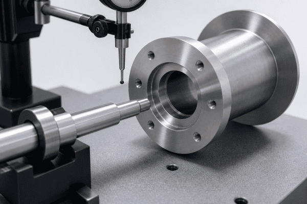
A spool hub must transmit rotation, hold the spool concentric with the winder axis, and release or clamp the spool during bobbin changeover. The hub body is relatively forgiving: a slightly thick flange or a substituted material may only affect mass or appearance. The bore and shaft interface is not forgiving. Clearance, taper, surface finish, and clamping behavior all act directly on fiber tension stability and layer registration.
Typical symptoms that trace back to this interface include axial or radial runout that changes with winding speed, gradual drift of the wound package toward one flange, clamp marks on a shaft, spool wobble after a changeover, and unexplained tension spikes near the end of a spool. Before replacing a hub, it is worth confirming whether the problem follows the hub, the shaft, or the pairing.
Checks to Run Before Ordering Customized Spool Hubs
Measure the shaft, not the old hub
The old hub bore reflects what the shaft looked like when the hub was made, not what it looks like now. Shafts wear, get polished, get re-machined, or get replaced with a nominal equivalent that is not dimensionally identical. Measure the actual shaft at multiple axial positions and at more than one angular orientation. A shaft with a small bend, taper, or local wear band will produce inconsistent readings that matter for fit selection.
- Outside diameter at the bearing or support region and at the full hub seat length
- Roundness or ovality across several angular positions
- Straightness or runout over the hub seat length
- Surface condition: scoring, corrosion, polishing, burrs, or keyway damage
- Any shoulder, step, key, flat, taper, or threaded section the hub must engage
Confirm how the hub is retained
Optical fiber winding spool hubs are retained in several different ways, and the bore design follows from that choice. Common arrangements include a sliding fit with an end clamp, a taper or collet interface, a keyed or splined drive, a set screw or clamp collar bearing on a relieved section of shaft, and shoulder-seated hubs where axial position is set by a face rather than by the bore. Removing the hub from the drawing without confirming the retention method is a frequent source of first-article rejection.
Look at what the hub is expected to do
A hub on a low-speed take-up station and a hub on a high-speed precision winder are not the same problem. Speed, spool mass when full, acceleration and deceleration profiles, and required changeover time all constrain bore tolerance and clamping method. So does the operating environment: a hub that runs warm, sees cleaning solvents, or sits in a humid area may need different surface treatment or a different base material than one in a clean, stable bay.
Interpreting Bore and Shaft Measurements
Clearance that is too loose
Excess clearance allows the spool to shift under load. The effect is often periodic rather than constant: the package drifts, then corrects, as the hub finds a new position against the shaft. In severe cases the spool can rotate slightly relative to the shaft during rapid deceleration. Loose fits are sometimes masked by a clamp that is tightened harder than intended, which introduces its own problems at the shaft surface.
Clearance that is too tight
An interference or near-interference fit can be correct for some hub designs, but only when the hub and shaft materials, wall thickness, and assembly method are chosen for it. A hub that must be pressed on and pried off will generate handling damage, slow changeovers, and risk distorting a thin-wall hub enough to affect spool seating. If a hub is difficult to remove, that is a design issue, not an operator issue.
Bore geometry problems
Diameter alone does not define a bore. A hub can measure correctly on diameter while still producing runout because of:
- Bore-to-flange-face perpendicularity error, which tilts the spool
- Bore-to-outer-datum concentricity error, which offsets the spool axis
- Taper or a barrel-shaped bore from machining or thermal distortion
- Localized high spots, burrs, or a raised edge at the bore entry
- Rounding or damage from repeated assembly against a sharp shaft feature
These conditions produce runout even when the fit feels correct by hand. The practical diagnostic is to indicate the assembled hub and spool on the winder axis and compare axial and radial runout at the flange and at the spool seat. If runout appears only after assembly, the interface geometry is a strong candidate.
Alignment and Runout Verification
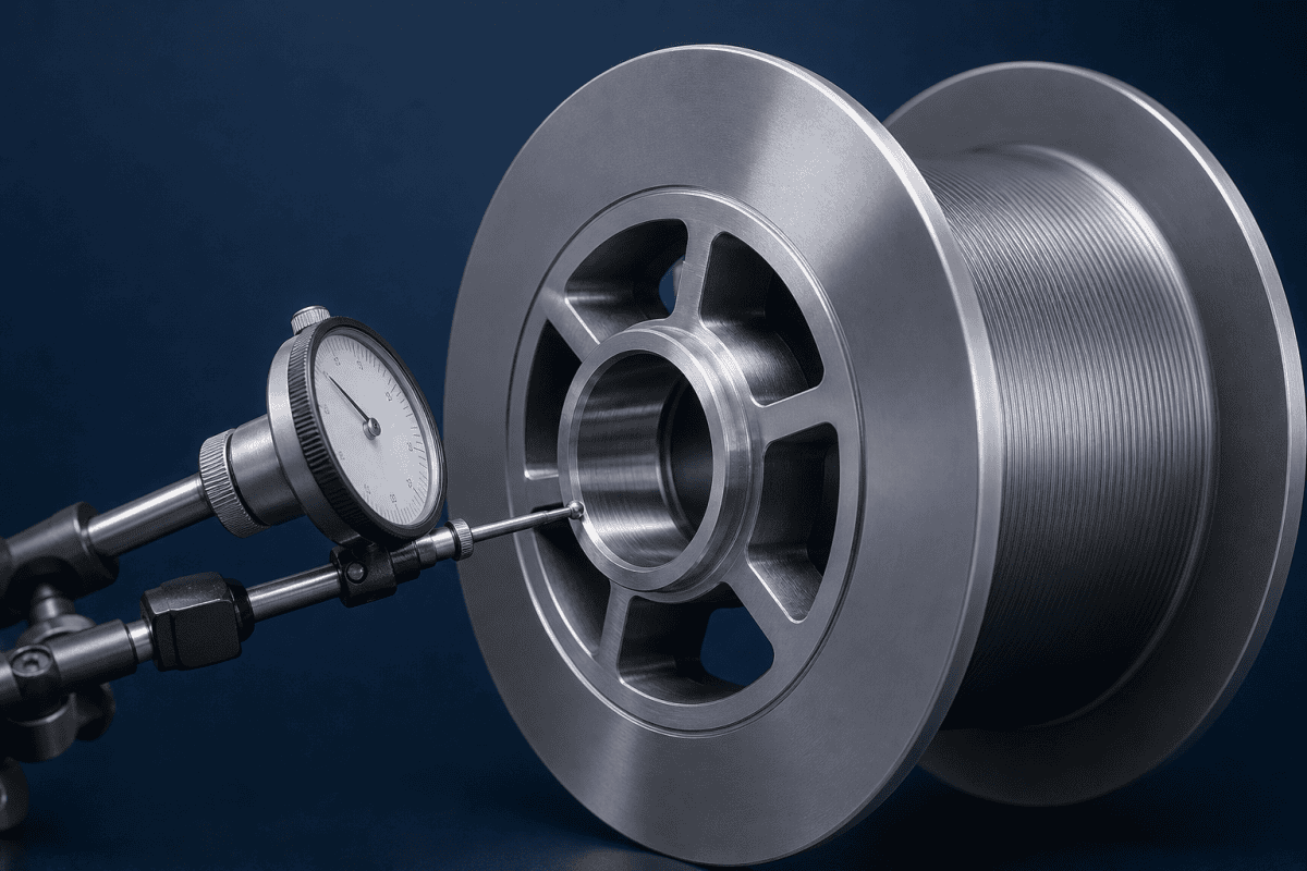
Once the basic bore and shaft measurements are recorded, the next step is to verify how the assembly behaves when it is actually mounted. Static measurements can look correct while dynamic behavior reveals a problem that only appears under rotation. A dial indicator set against the hub flange and against the spool seat, with the hub rotated by hand and then driven at production speed, will show whether runout is consistent or whether it grows with rpm. If runout increases with speed, the likely causes are an unbalanced spool, a bent shaft, or a hub that is not seating squarely on its datum face. Addressing the bore and shaft interface first will confirm whether the remaining error is dynamic or geometric.
Material and Surface Considerations at the Interface
Material choice for a hub is governed by function, not by habit. A hub that only locates a lightweight spool at low speed has different requirements from one that transmits torque through a clamped bore under repeated changeover. Relevant factors include thermal expansion relative to the shaft, galling tendency when aluminum runs against stainless, hardness and wear resistance at the bore, mass and inertia, chemical exposure from cleaning agents, and whether the part must be non-marring at the shaft surface.
Aluminum is often selected for reduced inertia and ease of machining, and aluminum OVD parts illustrate how process-adjacent components can be produced in that material where mass matters. For hubs specifically, aluminum against a hard steel shaft can gall or pick up if the fit is tight and lubrication is absent, so surface treatment or a different bore strategy may be appropriate. These choices should follow from the operating conditions you supply, not from a default preference.
Writing a Clear Sourcing Request for Custom Fiber Spool Hubs
A drawing plus a short operating note produces far better results than a drawing alone. The note does not need to be long; it needs to resolve the questions a machinist and an engineer would otherwise have to guess.
What to include
- Annotated shaft dimensions at the hub seat, including fit class or target clearance
- Retention and clamping method, with any key, flat, taper, or thread defined
- Bore-to-face and bore-to-OD geometric controls that matter for runout
- Material and any surface treatment, with the reason stated
- Operating speed range, spool mass when full, and changeover method
- Environment: temperature range, cleaning agents, humidity, and contamination risk
- Sample quantity and whether a first-article check is expected
What to flag as open
If the original hub is unavailable or undocumented, say so explicitly. A supplier working from a worn sample plus measured shaft data can propose a bore and retention strategy, but only if they know which dimensions are fixed by the equipment and which are open to redesign. This is the situation where reverse engineering adds the most value, and the general workflow is described in this guide to supplier qualification for preform equipment parts, which applies the same logic to closely toleranced preform equipment parts.
Common Winding Faults Linked to the Hub Interface
When a hub is not matched to its shaft, the resulting faults often show up as winding defects rather than as obvious mechanical failures. Recognizing the pattern can save unnecessary replacement of unrelated components. Typical symptoms include layer registration drift toward one flange, periodic tension spikes that correlate with spool rotation, and visible wobble that increases as the package builds. For a broader look at how the cutter and clamp assembly interacts with the hub during changeover, see the guide to cutter assembly replacement specifications.
Troubleshooting Runout and Slippage on the Winder
When a hub-related fault appears, separate possible causes from confirmed ones before ordering replacements. Useful verification steps include:
- Possible cause: hub bore fit. Verify by swapping in a known-good hub on the same shaft and repeating the runout measurement.
- Possible cause: shaft wear or bend. Verify by indicating the bare shaft over the seat length without a hub installed.
- Possible cause: retention or clamp not seating. Verify by inspecting contact marks and confirming the hub seats against the intended datum face, not against a burr or shoulder fillet.
- Possible cause: spool-to-hub seating. Verify by indicating the spool directly; error here imitates a hub fault.
- Possible cause: hub distortion from over-tightening. Verify by measuring bore roundness before and after clamping.
If runout correlates with winding speed rather than with the hub position, the interface may be amplifying a separate imbalance or tension control issue. Recording runout at several speeds helps distinguish a geometric fault from a dynamic one.
Where Spool Hub Work Fits in a Wider Maintenance Plan
Hubs are usually replaced as part of a broader take-up station refresh, alongside the components that handle fiber at the end of the line. The optical fiber winder clamp and cutter assembly is one example of a take-up area component where changeover handling and alignment matter as much as the hub fit. Treating these parts as a coordinated set, rather than replacing one at a time, tends to reduce repeat faults caused by a new hub compensating for a worn mating part.
For teams that need non-standard hub geometries, modified bore features, or drawing-based production of parts no longer offered by the original equipment supplier, OEM/ODM machining services cover one-off and small-batch manufacture from supplied drawings or measured samples.
Hub Bore Tolerance and Fit Class
Assigning a fit class to the bore is easier when the operating conditions are known. A controlled sliding fit with a defined clearance band suits hubs that are removed frequently, while a light interference fit may be appropriate for hubs that stay mounted for long periods. The bore tolerance should always be stated with the shaft tolerance and the retention method, because a clearance that works with an end clamp may be too loose for a set screw arrangement. When reviewing an existing specification, check whether the fit class was chosen for the hub material and wall thickness or simply carried over from a legacy drawing. A hub with a thin wall can distort under clamping load, so the as-machined bore tolerance may need to be tighter than the assembled requirement.
Pitakonan sing Sering Ditakoni
Can I specify a hub by bore diameter alone?
No. Bore diameter sets clearance, but perpendicularity to the flange face, concentricity to the spool seat, bore length, entry chamfer, and surface finish all affect assembled runout. Two hubs with the same bore diameter can behave very differently on the same shaft.
Should the hub be a press fit or a sliding fit?
It depends on how the hub is retained and how often it is changed. Frequent changeover favors a controlled sliding or clamped fit with a defined datum. Press fits can work where the hub stays in place, but they require the hub and shaft materials and wall thickness to be evaluated together, and they make removal a planned operation rather than a routine one.
What if I only have the old hub and no drawing?
Supply the worn hub, accurate shaft measurements over the seat length, and the retention method. Note which dimensions are constrained by the equipment and which can be adjusted. A supplier can then propose a bore and clamping approach instead of copying wear into the new part.
Does changing the hub material change the required bore tolerance?
It can. Thermal expansion differences, galling tendency, hardness, and the hub’s wall stiffness all influence how a given fit behaves in service. If you change from one material to another, revisit the fit and surface treatment rather than carrying the previous tolerance forward unchanged.
FAQs About Optical Fiber Winding Spool Hubs
For more detail on the components that work alongside the hub during bobbin changeover, the article on optical fiber bobbin changeover components covers custom clamp and cutter parts. A separate guide on optical fiber take-up winder clamp replacement explains dimensional and grip checks that pair well with hub inspection. For a standards reference on limits and fits, ISO 286-1 from the International Organization for Standardization provides the tolerance grade definitions used in most bore and shaft specifications.
Langkah Sabanjure
To move from inspection to a workable quotation, gather the shaft measurements, retention details, runout requirements, and operating conditions for each hub position. Send those along with any available drawings, photos of the worn part, and a note on which dimensions are fixed by the equipment, and contact our team to review the bore and shaft interface and discuss a suitable manufacturing approach.
