
Knowledge
Reverse engineering burner nozzle: Nozzles for Discontinued Optical Fiber Preform Torches
Oct
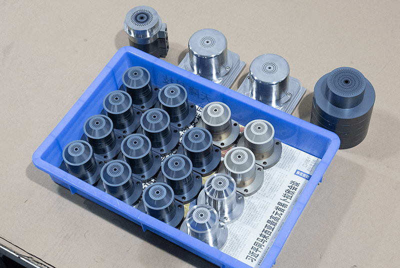
When a preform lathe or deposition torch reaches the end of its production life, the equipment itself is rarely the first problem. The real bottleneck usually appears later, when a burner nozzle, faceplate insert, or gas distribution component needs replacement and the original supplier no longer offers it. The reverse engineering burner nozzle process for discontinued optical fiber preform torches turns a physical sample or incomplete drawing set into a documented, manufacturable component that restores the deposition process without guesswork.
This work sits at the intersection of metrology, materials engineering, and process knowledge. It is not simply copying a shape. A nozzle that looks identical but has different hole geometry, surface finish, or thermal expansion behavior can shift flame shape, soot deposition, and eventually preform quality. For engineers and maintenance teams, the goal of reverse engineering burner nozzle components is a documented, verifiable replacement — not a visually similar part.
Why Discontinued Torch Components Become a Production Risk
Optical fiber preform equipment often stays in service far longer than the commercial lifecycle of its burner hardware. Lathes and deposition stations may run for decades, while torch models are discontinued, suppliers consolidate, and original drawings are lost or never released to the end user.
Several situations force a reverse engineering burner nozzle decision:
- The OEM has discontinued the torch model or the specific nozzle variant.
- Drawings exist but lack critical dimensions, tolerances, or material specifications.
- Only a worn or partially damaged sample remains available for measurement.
- The process has been modified, so a like-for-like replacement no longer matches current operating conditions.
- Lead times or minimum order quantities from remaining sources are impractical.
In each case, the engineering question is the same: which characteristics of the original component actually matter to the process, and which can be reasonably adjusted without affecting deposition behavior?
Distinguishing OVD, VAD, and MCVD Nozzle Requirements
Any reverse engineering burner nozzle project must start with process identification. OVD (outside vapor deposition), VAD (vapor axial deposition), and MCVD (modified chemical vapor deposition) use different torch configurations, flame geometries, and thermal environments. Components are not interchangeable between them, and a nozzle reverse-engineered for one process should not be assumed to suit another.
OVD and VAD torches typically use multi-channel designs that separate fuel, oxygen, and carrier gases, and the nozzle geometry strongly influences flame shape and particle deposition. MCVD torches operate against a rotating substrate tube with different thermal and positioning constraints. Even within OVD, auxiliary tail burners and main deposition burners have different functional priorities.
For a practical comparison of how nozzle design differs across these processes, the guide on which OVD, VAD, and MCVD burner parts need separate specifications is a useful reference before defining reverse engineering burner nozzle requirements. Getting the process category wrong at the start is one of the most expensive mistakes in this work.
What Reverse Engineering a Burner Nozzle Actually Involves
A structured reverse engineering burner nozzle project moves through four stages: documenting the existing component, establishing the material specification, reconstructing the drawing package, and verifying fit and function before full production. Skipping or compressing any stage usually shows up later as a fit problem or a process deviation.
1. Documenting the Existing Component
The first stage is dimensional and condition assessment. A worn nozzle cannot be measured as if it were new, because erosion, thermal distortion, and soot buildup alter critical features. Where possible, teams should combine:
- Direct measurement of the sample using appropriate metrology.
- Comparison against any surviving drawings, even partial ones.
- Review of maintenance records showing how the component performed before removal.
- Inspection of mating parts such as the torch body, gas manifold, and mounting interfaces.
Hole patterns, channel diameters, concentricity, and face flatness are typically the features most sensitive to process performance. Where a sample is degraded, it may be necessary to reconstruct intended geometry from the mating hardware and process requirements rather than from the worn part alone. This documentation stage is the foundation of any reverse engineering burner nozzle effort; without it, downstream measurement loses its reference point.
2. Establishing the Material Specification
Material selection cannot be inferred from a product category or a part name. The correct material depends on the component’s function, its temperature exposure, the chemical environment, and the engineering requirements of the torch. A faceplate, a gas channel insert, and a mounting flange may all require different materials even within the same torch.
Useful inputs for material decisions in reverse engineering burner nozzle work include:
- Which gases or vapors contact the component, and at what conditions.
- Whether the part experiences direct flame exposure or is shielded.
- Thermal cycling frequency and expected service environment.
- Required dimensional stability at operating temperature.
- Machinability and joining requirements for the chosen design.
Where the original material is unknown, elemental analysis or hardness testing of a sample can narrow the options, but the final choice should be confirmed against the actual operating environment. The broader material and reverse-engineering considerations are covered in the custom OVD and VAD burner sourcing guide.
3. Reconstructing the Drawing Package
A manufacturable reverse engineering burner nozzle needs more than a sketch. A complete package typically includes:
- Annotated 2D drawings with critical dimensions and tolerances.
- A defined datum structure so concentricity and alignment can be controlled.
- Material specification with any required condition or treatment.
- Surface finish requirements for gas-exposed and sealing surfaces.
- Inspection criteria the supplier can verify before shipment.
This is the stage where make-to-print torch parts become realistic. Once the drawing is defined, the component can be produced repeatedly without depending on the original sample, which is essential for long-term spare-parts planning. Suppliers experienced in machining multi-channel OVD burner bodies often handle this drawing reconstruction as part of the quotation process.
Consistent documentation also matters when a design is derived from a physical sample rather than an original file. The workflow described in this guide to avoiding dimensional errors in deposition burner reverse engineering outlines the checks that keep the reconstructed drawing reliable.
4. Verifying Fit and Function Before Full Production
Before committing to a production run, a first-article verification is advisable. This may involve dimensional inspection against the drawing, fit checks against the torch body, and — where the user’s procedures allow — controlled evaluation under normal operating conditions. Any process parameter changes should follow equipment documentation and be handled by qualified personnel, not introduced as part of a component trial.
For MCVD heating burners specifically, the component often has to satisfy both thermal and gas-flow requirements at once. The evaluation checklist in this guide to custom replacement of Nextrom MCVD heating burner components is a useful companion during first-article review.
Critical Features That Determine Reverse Engineering Burner Nozzle Success
Not every dimension carries equal weight. In reverse-engineered burner nozzles, the following features usually deserve the closest attention:
- Gas channel geometry: diameter, length, and transitions affect flow and pressure balance.
- Hole pattern and spacing: determines flame distribution and deposition uniformity.
- Concentricity: misalignment between channels can shift flame position and affect preform symmetry.
- Face flatness and surface finish: influences sealing, soot buildup, and long-term stability.
- Thermal expansion behavior: the assembly must remain dimensionally stable across the operating cycle.
The relationship between nozzle precision and preform outcomes is not hypothetical; it is one of the main reasons reverse engineering burner nozzle work should be treated as an engineering project rather than a machining job. Small geometric deviations matter over the life of a deposition campaign, and the effect is measurable in deposition uniformity and in the resulting optical properties of the preform.
The same principle appears in adjacent fields such as photonics fabrication, where dimensional control at the micron scale determines optical performance. Reference material from organizations like SPIE, the international society for optics and photonics, reinforces how tightly process geometry and device performance are linked — a useful framing when explaining to stakeholders why burner nozzle tolerances deserve attention.
Common Pitfalls in Reverse Engineering Burner Nozzle Work
Several recurring problems reduce the value of a reverse engineering burner nozzle effort:
- Measuring a worn part as if it were nominal. Erosion and distortion can be mistaken for original design intent.
- Ignoring the mating interface. A nozzle that fits the sample but not the torch body is unusable.
- Assuming material from appearance or category. Visual similarity does not confirm alloy or grade.
- Omitting tolerances from the drawing. Without them, suppliers cannot control the features that matter.
- Treating OVD, VAD, and MCVD parts as equivalent. Process differences change design priorities.
- Skipping first-article verification. A dimensionally correct part can still perform differently if assembly or sealing is affected.
Each of these is preventable with a structured approach and clear communication between the maintenance team, process engineers, and the machining supplier. A second opinion on the disassembly and measurement sequence is often worthwhile before the reverse engineering burner nozzle drawing is signed off, and it is cheaper than discovering the error after production.
It is also worth checking whether a similar component already exists as a standard item rather than a custom build. A parts-level review of OVD, VAD, and MCVD burner parts that need separate specifications can reveal whether the nozzle is a truly bespoke design or a variant of a known family.
Preparing a Clear Sourcing Request
A well-prepared inquiry speeds up quotation and reduces the risk of a mismatched part. Useful information to provide includes:
- Process type (OVD, VAD, or MCVD) and the burner’s role in the torch assembly.
- Available drawings, sketches, or a sample component for measurement.
- Critical dimensions and any known tolerances, even if approximate.
- Material requirements, or the operating conditions needed to determine them.
- Gas connections, mounting interfaces, and any space constraints.
- Quantity needed for first article and for ongoing spares.
The more completely the original component is described, the less room there is for a supplier to guess. Where a drawing is not available, a reverse engineering burner nozzle supplier should be able to work from the sample plus the process information listed above.
For parts that need a full dimensional review, the verification steps in this guide to Nextrom OVD burner nozzle replacement dimensions and connections are a useful template for the information worth capturing before the first-article comparison. VAD users will find a parallel checklist in this article on drawing-based sourcing of Nextrom VAD burner replacement parts.
Suppliers that handle custom and non-standard components can often work from a sample plus partial documentation. For projects that combine nozzle and burner-level work, the scope in this guide to sourcing custom OVD and VAD burners shows how a single engineering package can cover multiple components.
Where a heating burner rather than a deposition burner is involved, the requirements differ and the review should reference the component expectations covered in this article on custom MCVD heating burner component evaluation.
For custom MCVD burner nozzles built from customer drawings, the drawings plus operating details are the same inputs that any reverse engineering burner nozzle project relies on, as described in this guide to supplying custom MCVD burner nozzles to drawings.
Design Verification and Documentation Standards
Reverse engineering sits inside a wider engineering-discipline framework that treats verification and traceability as part of the deliverable. The principles are broadly consistent with the guidance published by ASME on codes and standards, which reinforces the value of a documented drawing package, defined datums, and inspection criteria rather than verbal agreements.
For a reverse engineering burner nozzle, the practical translation of that discipline is straightforward:
- Every critical dimension has a stated tolerance.
- Every material is specified by grade, not by description.
- Every inspection is defined before production begins.
- Every deviation is recorded and reviewed, not absorbed silently.
Teams that adopt this structure typically find that a single well-documented reverse engineering burner nozzle definition can be reused for years, even after the original supplier has disappeared from the market.
Total Cost of Ownership Versus Lead Time
Discontinued burners create a trade-off between lead time and total cost of ownership. Rushing the reverse engineering burner nozzle process to shorten downtime often produces a component that fits but performs differently, leading to rework, lost preform yield, and a second replacement cycle. Investing in measurement, material confirmation, and first-article inspection usually costs less over the life of the torch than a fast, unverified copy.
A practical way to think about it is to separate the one-time engineering cost from the recurring production cost. The reverse engineering burner nozzle drawing and first article are one-time investments; the per-part cost depends on geometry, material, and quantity. Documenting everything up front means the second, third, and tenth replacement all benefit from the same engineering work.
Another consideration is obsolescence planning. When a torch model is discontinued, the spare-parts pipeline usually narrows before it disappears entirely. Building a reverse engineering burner nozzle package while a functioning sample is still available is far easier than reconstructing the part from an already-failed asset. Teams that capture dimensional and material data in advance typically face less downtime when the final OEM parts run out.
Extending the Approach to Other Torch Components
Nozzles are the most common component to fail, but they are rarely the only one. Faceplates, inserts, mounting hardware, and gas distribution bodies often share the same discontinued-supplier problem. Once a reverse engineering burner nozzle process is in place, the same method can be applied to adjacent components without starting over.
The key is to keep the documentation consistent across components. A shared datum structure, a common material specification format, and a single inspection template make the second and third component far faster to define than the first. This is where a reverse engineering burner nozzle program turns into a broader replacement-parts strategy.
It also helps to group components by function rather than by part number. Gas delivery components, thermal components, and structural or mounting components each have different critical features, so the drawing template can be adapted per group while the overall reverse engineering burner nozzle methodology stays the same.
FAQ
Can a reverse-engineered nozzle match the original exactly?
Exact duplication is possible only when the original drawing and material specification are available. In most discontinued-torch cases, the goal of reverse engineering burner nozzle work is functional equivalence: matching the features that affect deposition while documenting the tolerances and material needed for repeatable production. Where the original is worn, intended geometry may need to be reconstructed from mating parts and process requirements.
How do we decide the material for a replacement nozzle?
Base the decision on the component’s function, its temperature exposure, the chemical environment, and the engineering requirements of the torch — not on appearance or a broad product category. Where the original material is unknown, analysis of a sample can narrow the options, but the final choice should be confirmed against actual operating conditions.
What if we only have a damaged sample and no drawing?
A physical sample plus partial documentation is often enough to begin. The supplier should measure the sample, assess which features are reliable versus worn, and reconstruct a drawing from the sample, mating components, and process inputs. First-article inspection then confirms the result before production quantities are made.
Are OVD, VAD, and MCVD torch components interchangeable?
No. Each process uses different torch configurations, thermal environments, and gas delivery arrangements. A nozzle designed for one process should not be assumed to work in another. Process identification should be the first step in any reverse engineering burner nozzle project.
Next Step
A reverse engineering burner nozzle project for a discontinued preform torch is manageable when the process type, critical features, and material requirements are defined before machining begins. The most reliable path is to share what you have — a sample component, a partial drawing, dimensions, material notes, and operating conditions — so the component can be evaluated as a complete engineering requirement rather than a shape to copy.
To move forward, contact our team with your drawings, measurements, or sample details and the operating context of the torch, and we can discuss the most practical route for custom or make-to-print replacement components. Reusing the same reverse engineering burner nozzle documentation across an entire torch assembly is often the quickest way to restore stable deposition performance and to protect the preform process from the next spare-parts shortage.
