
Knowledge
Controlling Preform End-Taper Cracking in OVD: Thermal & Hardware Solutions
Sep
There is no sound more disheartening in an optical fiber preform bay than the sharp crack of a soot boule splitting near the end of a multi-hour OVD deposition run.
Most catastrophic cracks do not originate along the active cylindrical body of the preform. They almost invariably initiate at the end tapers (the transition zones near the bait rod or handle), propagating inward along the soot interface within seconds.
When a large soot boule approaches target diameter, thousands of dollars in chemical precursors (SiCl₄ and GeCl₄), combustion gases, and lathe run-time are on the line. Diagnosing end-taper failure requires looking at the thermal dynamics of the burner turnaround stroke and the mechanical hardware maintaining thermal equilibrium.
Boule Thermal Profile at Turnaround:
[ Central Cylinder: Stable 1350°C - 1450°C ] ──> [ End Taper: Rapid Drop < 1150°C ]
                                                        │
                                                        ▼
                                           Severe Radial Tensile Stress
                                                        │
                                                        ▼
                                           Micro-Fissures ──> Catastrophic Crack
1. The Physics of Turnaround Thermal Shock
During standard Outside Vapor Deposition, the primary deposition torch travels back and forth along the rotating mandrel. At each end of the stroke, the carriage must decelerate, reverse direction, and re-accelerate.
Even with optimized CNC motion profiles, the time the main flame spends off the soot shoulder creates a rapid surface temperature drop.
-
The Thermal Expansion Differential: The outer soot layers cool at a much faster rate than the dense inner layers adjacent to the core rod. This sudden thermal gradient induces severe radial tensile stress on the loosely bonded silica matrix.
-
Deposition Efficiency Plunge: When the local soot surface temperature falls below approximately 1200°C, the chemical hydrolysis of SiCl₄ slows down. Particles depositing in this temperature dip exhibit reduced density, creating a structurally porous, brittle “chalk line” at the taper that serves as a stress concentration notch.
-
Ambient Cleanroom Infiltration: The ends of the deposition chamber are vulnerable to cold ambient draft eddies, which further chill the taper edges unless shielded by a constant gas curtain.
2. Why Process Recipe Adjustments Are Not Enough
Engineers often attempt to solve end-taper cracking through software: extending the burner stroke travel, increasing carriage dwell times, or ramping up hydrogen (H₂) flow near the margins.
However, software fixes usually introduce secondary failure modes:
| Software/Recipe Adjustment | Unintended Consequence on the Preform |
| Longer Carriage Dwell Time | Localized soot overheating leads to premature vitrification (glass scaling), causing flame deflection on subsequent passes. |
| Increased Fuel Gas at Ends | Distorts the core-to-cladding refractive index profile (Δn) near the usable shoulder, reducing total effective fiber yield. |
| Wider Stroke Margins | Wastes expensive chemical precursor vapor into the exhaust exhaust hood without depositing on the target rod. |
The reliable engineering solution is not to distort the main burner’s deposition flame, but to decouple deposition chemistry from taper temperature management using dedicated auxiliary thermal hardware.
3. Hardware Remediation: The Role of Auxiliary Tail Burners
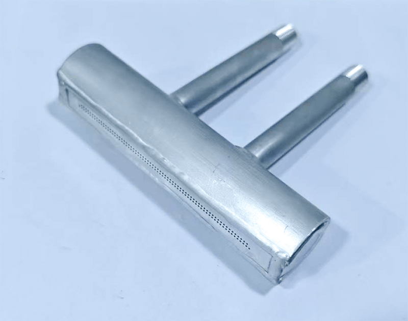
An auxiliary tail burner (or linear oxygen distribution manifold) is mounted at the preform ends to provide stationary or synchronized thermal stabilization.
Gas Delivery Dynamics:
[ Dual Symmetrical Inlets ] ──> [ Equalized Chamber Header ] ──> [ Micro-Orifice Array ] ──> Uniform Thermal Blanket
Rather than depositing soot, these units deliver a steady, soft heating flame alongside a uniform shielding gas curtain:
-
Eliminating the Thermal Valley: By maintaining baseline surface temperature at the end tapers while the primary torch travels to the opposite end, auxiliary burners keep the soot matrix within an elastic thermal window, eliminating tension spikes.
-
Uniform Static Pressure via Dual Inlets: Single-inlet gas pipes inevitably exhibit gas pressure drop along their length, resulting in weak flame at the far end and turbulent jets near the feed port. A dual-inlet header equalizes internal manifold pressure, guaranteeing that every micro-orifice in the linear array discharges gas at an identical velocity.
-
Preventing Soot Boundary Recirculation: A linear auxiliary oxygen curtain creates a positive-pressure air knife that prevents acidic reaction byproducts (HCl) and stray silica dust from curling back onto the torch mechanisms.
4. Machining Integrity and Alloy Selection
Because auxiliary tail burners operate in close proximity to the extreme radiative heat of 1400°C+ silica synthesis zones, their mechanical build quality directly influences flame stability.
-
Seam-Welded Alloy Construction: Standard bolted assemblies with gaskets fail under long-term cleanroom thermal cycling. Heavy-duty 316L Stainless Steel or High-Grade Titanium bodies with complete seam welding withstand continuous thermal expansion without gas leakage.
-
Burr-Free Micro-Orifice Drilling: Jagged discharge holes generate localized flame turbulence. Precision CNC drilling of the multi-row linear faceplate ensures a laminar gas shield that supports soot heating without blasting the delicate target boule.
Maximizing Preform Production Yield
End-taper cracking is an engineering challenge with a clear mechanical fix. Protecting your silica preforms from thermal shock stabilizes your process window, improves taper geometry, and increases the usable fiber kilometer yield per boule.
Explore our precision-machined OVD Auxiliary Tail Burner & Linear Oxygen Distribution Manifold designed for standard preform lathes, or pair it with our direct-fit Titanium OVD Burner Assemblies.
If your production line uses customized mounting geometries or unique gas delivery specs, browse our complete catalog of optical fiber equipment parts or contact our engineering team to machine custom components directly from your CAD drawings.
