
지식
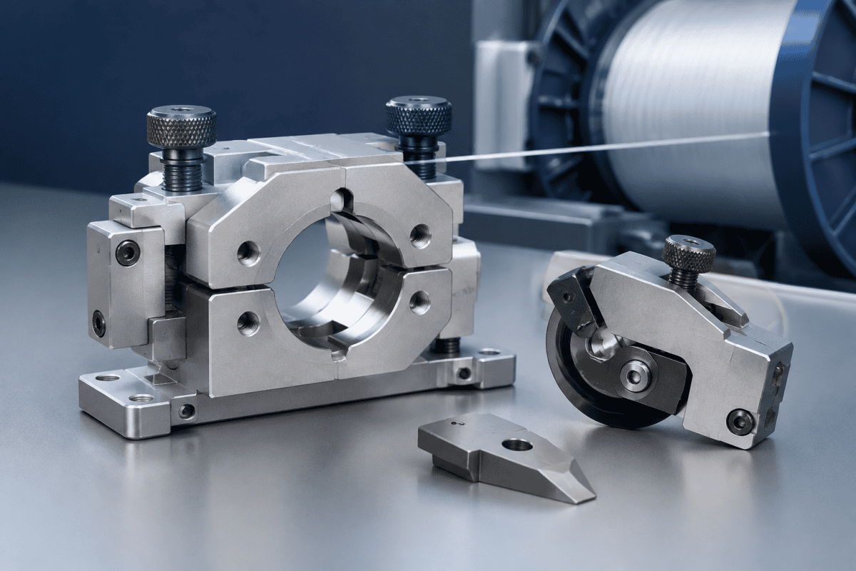
광섬유 보빈 교체 부품: 맞춤형 클램프 및 커터 부품
10월
광섬유 보빈 교체는 광섬유 인출 및 권취 사이클에서 짧고 고응력이 걸리는 구간이다. 권취 헤드가 감속하고, 광섬유가 포착 및 절단되며, 클램프가 권취된 보빈을 해제하고, 다음 맨드릴이 위치로 이송된다. 모든 동작은 반복 가능한 시퀀스 내에서 위치 결정, 파지, 절단을 수행해야 하는 기계 부품에 의존한다. 교체가 생산 기간당 수백 또는 수천 번 발생하기 때문에, 클램프와 커터 부품의 작은 치수 오차가 누적되어 불량 보빈, 광섬유 파단, 계획되지 않은 다운타임으로 이어진다. 이 글에서는 이러한 부품의 역할, 점검 방법, 정확한 소싱 요청 준비 방법을 설명한다.
이 주제는 확실히 다음 범주에 속한다 광섬유 보빈 교체 부품, 클램프 조 세트, 커터 블레이드 및 홀더, 가이드 요소, 그리고 이들을 와인더에 연결하는 장착 인터페이스를 포함하는 범주이다. 가장 일반적인 어셈블리 단위는 와인더 클램프 커터 어셈블리, 로, 광섬유 포착과 절단을 하나의 교체 가능한 그룹으로 결합하여 유지보수 후에도 두 기능 간 정렬이 유지되도록 한다. 이러한 부품이 기계에 잘 맞지 않으면 전체 권취 사이클이 예측 불가능해지며, 올바르게 지정된 세트는 생산이 요구하는 반복 가능한 시퀀스를 복원한다. 유지보수 팀은 시스템을 개별 부품의 집합이 아닌 하나의 전체로 취급해야 하는데, 각 인터페이스가 사이클의 다음 단계에 영향을 미치기 때문이다. 잘 문서화된 도면 세트는 향후 재조립을 간소화하고 잘못된 대체품 설치 위험을 줄인다. 따라서 신뢰할 수 있는 광섬유 보빈 교체 부품은 권취 수율과 광섬유 보호를 위한 핵심 수단이다.
광섬유 보빈 교체 부품이 교체 시퀀스에서 차지하는 위치
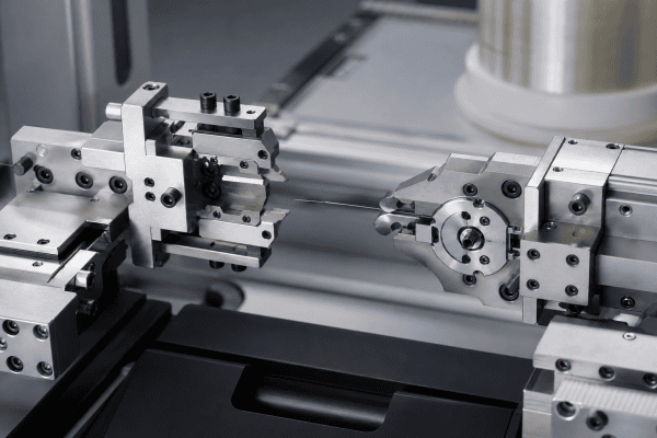
권취 와인더는 정해진 순서로 교체를 수행한다:
- 트래버스 또는 laying head가 광섬유를 이송 위치로 이동시킨다.
- 클램프 또는 캐처가 정의된 표면에 대해 광섬유를 포착한다.
- 커터가 제어된 지점에서 광섬유를 절단하여 다음 보빈을 위한 테일을 남긴다.
- 권취된 보빈이 해제되고 인덱싱되어 빠져나간다.
- 새로운 맨드릴 또는 튜브가 제시되고 결합된다.
각 단계는 그 이전 단계의 부품 형상에 의존한다. 클램프 조가 올바른 간극으로 닫히지 않으면 광섬유가 불균일하게 눌려 감속 중에 미끄러질 수 있다. 커터 블레이드의 날카로움이 떨어졌거나 잘못된 각도로 장착된 경우, 절단 동작이 거친 단면을 만들어 다음 권취 시작을 방해한다. 장착면이 마모되면 두 동작 모두 광섬유 경로에 대해 어긋나고, 교체 품질이 위치마다 일관되지 않게 된다.
이 시퀀스는 이러한 부품을 하나의 그룹으로 평가해야 하는 이유를 설명한다: 파지는 잘 하지만 절단이 불량한 커터를 가진 클램프는 여전히 교체 실패를 초래한다. 이들 간의 상호작용은 종종 개별 품목의 성능보다 더 중요하다. 실제로 공통 기준면을 공유하는 광섬유 보빈 교체 부품은 원래 형상을 유지하기 위해 함께 교체해야 한다. 부품을 매칭 세트로 추적하는 팀은 간헐적 결함이 더 적고 근본 원인 분석이 더 빠르다고 보고한다.
이 부품들이 다른 와인더 부품과 다른 점
클램프와 커터 부품은 수동적 가이드가 아니다. 이들은 세 가지 구별되는 요구사항을 가진 능동적 접촉 요소이다:
- 반복 가능한 위치 결정. 광섬유 경로는 매 교체 시마다 동일한 지점으로 재설정되어야 하므로, 다웰 홀, 숄더, 기준면과 같은 위치 결정 형상이 부품의 전체 크기보다 더 중요하다.
- 깨끗한 절단 형상. 커터 날 품질, 경사각, 블레이드와 카운터 에지 간의 간극이 광섬유가 깨끗하게 절단되는지 아니면 압괴되는지를 결정한다.
- 마모 및 오염 허용성. 코팅 잔여물, 폴리머 분진, 실리카 파편이 조 면과 블레이드 표면에 축적되어 유효 치수를 점진적으로 변화시킨다.
이러한 요구사항은 대략적인 형상만 일치하는 범용 대체품으로 구매한 클램프 또는 커터 부품이 초기에는 작동하다가 이후 성능이 저하되는 경우가 많다는 것을 의미한다. 익숙한 결과는 한 위치에서는 작동하지만 다른 위치에서는 간헐적으로 실패하는 교체이며, 이는 치수 검사 없이는 진단하기 어렵다. 도면 없이 소싱한 광섬유 보빈 교체 부품은 바로 이러한 패턴으로 실패하는 경향이 있는데, 핵심 위치 결정 치수가 가장 먼저 근사화되기 때문이다.
클램프 또는 커터 어셈블리 교체 전 점검 항목
부품이 마모되었다고 가정하기 전에 실제 상태를 확인하라. 다음 점검은 가능한 원인과 확인된 원인을 구분한다.
클램프 조(jaw) 상태
평탄화된 파지 표면, 광택이 나는 마모 패치, 박힌 파편, 둥글어진 진입 에지를 찾아라. 닫힌 간극을 측정하고 도면 값이 있으면 비교하라. 원래 간극으로 더 이상 닫히지 않는 조는 외관상 온전해 보여도 불균일하게 파지할 수 있다.
커터 날 및 장착 각도
육안만으로가 아니라 확대하여 블레이드를 검사하라. 약간 무뎌진 날도 광섬유를 절단할 수 있지만 거친 단면을 만들거나 더 높은 힘을 요구한다. 블레이드 시트의 프레팅, 버, 오염을 확인하라. 파편 위에 놓인 블레이드는 의도된 각도를 유지하지 못하기 때문이다.
위치 결정 형상 및 기준면
다웰 핀, 숄더 접촉부, 장착 홀은 정렬을 유지하는 기준점이다. 이러한 형상의 마모는 어떤 블레이드 또는 조 조정으로도 교정할 수 없는 어긋남을 초래한다. 의도된 접촉 영역 밖의 타원화, 버, 안착 자국을 확인하라.
인터페이스 및 액추에이터 상태
클램프 및 커터 부품은 공압 실린더, 캠, 스프링 또는 링키지와 상호 작용합니다. 액추에이터 스트로크, 복귀 이동 및 타이밍이 장비 문서와 일치하는지 확인하십시오. 형상 문제로 의심되어 교체된 부품이 실제로는 느린 액추에이터나 마모된 링키지에 반응하고 있을 수 있습니다.
광섬유 경로 확인
교체 후에는 광섬유가 클램프 및 커터에 대해 의도된 평면에 위치하는지 확인하십시오. 경로가 당겨지거나 오프셋되면 부품이 비대칭적으로 마모되고 체인지오버 신뢰성이 다시 저하됩니다.
재료 선정은 범주가 아닌 기능에 따라 결정된다
클램프 및 커터 부품은 구매 시스템에서 종종 함께 그룹화되지만, 재료 요구 사항은 다릅니다. 올바른 선택은 구성 요소의 기능, 온도 노출, 화학적 환경 및 기계 제조업체의 엔지니어링 요구 사항에 따라 달라집니다.
- 클램프 조 제어된 마찰, 치수 안정성 및 코팅 잔류물에 대한 내성이 필요합니다. 표면이 너무 단단하면 광섬유에 자국을 남기거나 손상시킬 수 있고, 너무 부드러우면 변형되어 그립을 잃습니다.
- 커터 블레이드 경도와 날 유지력이 필요하며, 압착이 아닌 절단하는 형상을 갖추어야 합니다.
- 홀더, 브래킷 및 바디 need stiffness and stable mounting faces, and may be produced in aluminum where mass and thermal behavior favor it.
It is not safe to infer a material from a broad product category or from a part’s appearance. Two visually similar clamp bodies may be specified in different alloys for different winder generations. The reliable approach is to work from the original drawing, a measured sample, or a clearly stated operating requirement. A guide such as the Nextrom VAD burner replacement parts sourcing guide covers similar material-selection logic for adjacent fiber production components, and the same discipline applies here: define the function first, then select the material. For broader context on fiber drawing and take-up, the Corning optical fiber overview provides background on the process these components support.
For components that are no longer supported by drawings, or that combine several functions in one body, OEM/ODM machining services allow production from a sample or a reconstructed drawing set. This is often the practical route for legacy winder positions where the original part number is unavailable. When optical fiber bobbin changeover components require reverse engineering, the drawing set should be rebuilt around functional dimensions rather than envelope shape, so that the replacement reproduces the original behavior instead of merely fitting the mounting space.
교체용 클램프 및 커터 어셈블리 소싱
A useful quotation request is specific. Vague inquiries produce generic responses, and generic responses produce parts that need rework. Include the following where available:
- Assembly identification: machine type, winder position, and any legacy part number.
- Dimensional data: drawings, or measured dimensions of the existing part, including locating features and datum surfaces.
- Functional description: what the clamp grips, where the fiber is cut, and the intended changeover direction.
- Material and surface requirements: specified alloy, hardness, coating, or an operating condition that drives the choice.
- Interface details: mounting hole pattern, actuator connection, and any gas or vacuum ports.
- Quantity and replacement pattern: single spare, position set, or planned rebuild kit.
Photographs help, but they are not a substitute for dimensions. A photograph can confirm a general shape; it cannot confirm a closed gap, a blade angle, or a dowel position. Where a drawing exists, send it. Where it does not, a measured sample plus a description of the failure mode gives a machinist far more to work with. See the approved internal reference on take-up winder clamp replacement: dimensions and grip checks and the optical fiber winder clamp & cutter assembly product page for related dimensional guidance.
일반적인 교체 증상 및 그 예상 원인
- Fiber slips during deceleration. Check clamp gap, jaw surface condition, and actuator force before replacing the jaw set.
- Ragged or crushed fiber end. Inspect cutter edge condition and blade seating; confirm the blade is at the specified angle.
- Changeover works on some positions but not others. Compare locating features and mounting faces across positions; this usually indicates a wear or alignment issue rather than a design fault.
- Progressive decline over weeks. Look for contamination buildup and fretting at datums, which change effective geometry gradually.
- Sudden failure after maintenance. Verify assembly orientation and seating; a part installed one step out of position can mimic a worn component.
Some of these symptoms overlap with burner-side and deposition-side issues that affect the fiber earlier in the process. If changeover problems appear alongside deposition variability, it is worth confirming that the upstream condition is stable, since burner concentricity and refractive index profile drift can change fiber characteristics in ways that later show up as handling problems at the winder. A systematic approach to troubleshooting optical fiber bobbin changeover components should always begin with the least invasive checks and move toward replacement only when dimensions confirm wear.
시간 경과에 따른 교체 신뢰성 유지
Clamp and cutter components respond well to a simple maintenance discipline:
- Keep jaw faces and blade seats clean; residue is a dimensional change, not just a cosmetic issue.
- Record the changeover interval and note when rejects begin to cluster, so wear trends become visible before failure.
- Replace clamp and cutter elements as a matched set when they share a common datum, rather than one at a time.
- Retain at least one known-good sample of each critical part for dimensional comparison.
Where several winder positions use similar but not identical parts, labeling and storage discipline prevents incorrect installation. This is a common and easily overlooked cause of intermittent changeover faults. A maintenance log that records the condition of optical fiber bobbin changeover components at each service interval turns scattered observations into a usable wear history. Over time, that history shows which parts fail first and whether the cause is mechanical wear, contamination, or an upstream process change.
자주 묻는 질문
도면 없이 클램프 또는 커터 부품을 교체할 수 있는가?
Yes, in many cases, provided the existing part can be measured accurately and the key functional dimensions are identified. Locating features, closed gap, and blade angle matter more than overall envelope dimensions. Reverse engineering from a sample is a normal approach for legacy components, but it should be done by someone who understands which dimensions carry the function.
와인더 클램프 커터 어셈블리는 기종 간 호환 가능한가?
Not automatically. Assemblies that look similar may differ in mounting pattern, actuator interface, fiber path position, or blade geometry. Compatibility has to be verified against drawings, dimensions, connection points, materials, and the specific application rather than assumed from appearance or product family.
문제가 클램프, 커터, 액추에이터 중 어디에 있는지 어떻게 알 수 있는가?
Isolate the functions. Test the clamp grip independently of the cut, inspect the cutter edge and seat separately from the jaw faces, and verify actuator stroke and timing against equipment documentation. This separates a confirmed dimensional or wear problem from a control or timing issue that a new part will not solve.
맞춤형 교체 부품 견적을 빠르게 받으려면 어떤 정보가 필요한가?
Drawings or measured dimensions, the operating function of each feature, material or surface requirements, interface details, and quantity. A description of the failure mode is also useful, because it often reveals which dimensions are most critical to reproduce.
다음 단계
If a changeover position is producing intermittent rejects or you are rebuilding a legacy winder, the fastest path to a usable part is a clear specification. Send your drawings, measured dimensions, material requirements, and a short description of the operating conditions through our quotation request page, and the team can review whether a standard optical fiber equipment part fits or whether a custom-machined replacement is the better route. A complete specification for optical fiber bobbin changeover components should always include the failure mode, because that single detail often determines which dimensions of those optical fiber bobbin changeover components are critical to reproduce.
