
지식
도면 및 장착 검증을 통한 SG Controls MCVD 버너 교체
10월
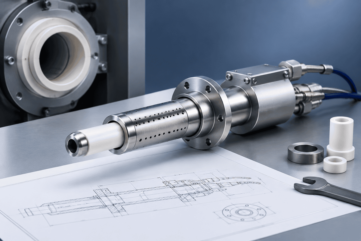
Replacing an SG Controls MCVD burner is rarely a simple swap. MCVD (Modified Chemical Vapor Deposition) relies on a precisely positioned heating torch that traverses the substrate tube, and the burner’s geometry, mounting interface, and gas delivery pattern all affect how heat is applied along the tube. When the original torch wears, clogs, or becomes unavailable, engineers and buyers often look for SG Controls MCVD burner replacement options that fit without introducing new process variables. The practical challenge is not finding a burner that “looks similar” — it is verifying the drawing, the mounting hardware, and the interface before any component is made or installed.
This article focuses on the verification steps that matter when sourcing an SG Controls MCVD burner replacement. It does not treat MCVD as interchangeable with OVD or VAD, where torches operate differently and are not governed by the same motion and heating requirements. If your process is OVD or VAD, the relevant component logic is described separately in the guide to OVD torch spare parts and fit verification.
Why the Burner Drawing Is the Controlling Document
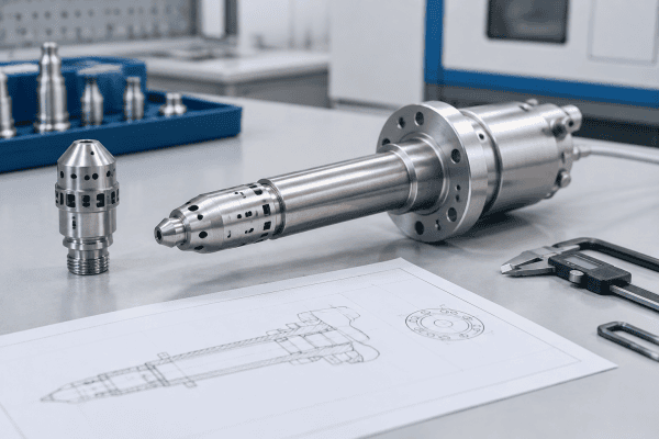
An SG Controls MCVD burner replacement is not a standalone part. It is positioned by a carriage or support, connected to gas lines, and aimed at a rotating tube. The drawing captures the features that determine whether a replacement will function: mounting hole pattern, locating surfaces, centerline height, angular orientation, and gas connection positions.
For an obsolete or undocumented burner, the drawing may not exist in usable form. In that case, an SG Controls MCVD burner replacement survey begins with a physical measurement of the original part. Key measurements include:
- Mounting interface: bolt circle or slot spacing, hole diameter and thread, dowel or locating pin positions, and any keyed surfaces.
- Bench reference: the distance from the mounting face to the burner centerline, sometimes called the center height or stack height. This dimension strongly influences where the flame sits relative to the tube.
- Burner face geometry: face width, number and arrangement of ports or slots, face curvature, and any shielding or shield-gas passages.
- Gas connections: port count, thread type, tube fitting style, and the position and angle of each inlet.
- Envelope and clearances: overall length, width, and any features that could interfere with the carriage or tube handling.
A replacement burner should be manufactured to a drawing that records these features, not to a photograph or a verbal description. If the original drawing is incomplete, a measured drawing can be produced from the old part and reviewed before manufacturing. This is a standard part of custom MCVD burner nozzle sourcing for non-standard or discontinued components.
It is also worth defining which features are truly critical versus merely convenient. A dimensional tolerance on the mounting hole pattern that is too tight can raise cost without improving the process; a tolerance that is too loose can allow the flame to shift. Review each drawing dimension with the person responsible for the process and mark those that affect the flame position, gas flow, or repeatability. That review, done before manufacturing, prevents most of the rework and finger-pointing that follows an installation that does not perform as expected.
In some cases the original drawing exists but reflects an older revision of the burner or the machine. Always confirm that the drawing and the machine on the floor are the same revision. If they are not, the measured survey becomes the authoritative document, and the old drawing is used only as a cross-reference.
Mounting Verification Checklist for SG Controls MCVD Installations
Mounting verification is where many SG Controls MCVD burner replacement projects fail. The new torch may have the right face pattern and gas ports but sit at the wrong height or angle, forcing the operator to compensate with carriage offsets or manual adjustments that were never part of the process recipe.
Before accepting an SG Controls MCVD burner replacement, verify the following against the machine interface:
1. Carriage and Support Interface
- Does the mounting plate or bracket accept the SG Controls MCVD burner replacement without adapter plates that change the centerline?
- Are the bolt holes aligned, and are the threads correct for the machine’s hardware?
- Is there a locating feature — a pin, shoulder, or machined step — that repeats the burner position after each removal? If the original relied only on bolts, the SG Controls MCVD burner replacement should not introduce a new locating scheme without engineering review.
2. Centerline and Traverse Alignment
- With the burner mounted, does the flame centerline align with the substrate tube’s centerline within the tolerance defined by your process documentation?
- Does the traverse axis move the burner parallel to the tube, or does the SG Controls MCVD burner replacement introduce a tilt that changes the heat profile along the deposition length?
- Are there shims or adjustable stops in the original setup? If so, the replacement should work with them rather than require a new adjustment method.
3. Gas Connection Mapping
MCVD torches often use multiple gas lines for fuel, oxygen, and sometimes shield or carrier gases. The physical layout of the inlets on the SG Controls MCVD burner replacement must match the routing of the existing hoses and manifolds. A burner with the correct ports but a different inlet geometry can force hose rerouting, which may affect flow characteristics or create strain on fittings.
Confirm that each inlet on the drawing is identified with its intended gas service, and that the SG Controls MCVD burner replacement inlet positions correspond. If the original burner had a specific inlet orientation to clear the carriage or tube handling path, that orientation must be preserved.
4. Thermal and Clearance Envelope
The SG Controls MCVD burner replacement should fit within the same thermal envelope as the original. Check that nearby components — tube seals, exhaust ducts, carriage covers, and sensors — are not exposed to a different heat pattern because the new burner extends further, sits closer, or radiates differently. This is a mechanical clearance question as much as a thermal one, and it should be reviewed with the equipment documentation and qualified process personnel.
Also check the cold clearance against the hot clearance. A burner that clears the tube when the system is cold may interfere once the tube, carriage, and burner have expanded. Where the original design used a specific gap or shim stack, replicate it rather than approximate it, and document the as-installed dimensions for the next replacement cycle.
5. Documentation and Repeatability
Record the final installed dimensions: centerline height, angular orientation, inlet positions, and any shims used. This record becomes the reference for the next replacement and for verifying that a new burner matches the one it replaced. Without it, every replacement becomes a new survey, and the risk of an SG Controls MCVD burner replacement drifting from the original process setup increases with each cycle.
Materials and Fabrication Considerations
MCVD heating burners operate in a high-temperature environment and are exposed to the gases used in the process. Material selection depends on the specific component — faceplate, body, gas manifold, or mounting flange — and on the temperature, chemical exposure, and mechanical loads at that location.
Do not assume that a material used in one burner is suitable for another. A material that performs well in an OVD torch may not be appropriate for an SG Controls MCVD burner replacement if the operating conditions differ. When requesting an SG Controls MCVD burner replacement, specify the function of each component and any known material requirements from the original drawing or maintenance records. If the material is unknown, discuss the operating conditions with the supplier rather than selecting by appearance.
For burners that must dissipate heat or maintain dimensional stability, the fabrication method also matters. Precision machining of the face and gas passages affects how the flame is distributed, and the mounting features must be machined to the drawing so that installation does not require field modification. The general principles of burner precision are discussed in the article on custom MCVD burner nozzle drawings and operating details, and many of the verification habits apply here as well.
Where the original burner used a specific alloy, coating, or surface finish, those details belong on the drawing. Surface finish on the face can affect heat transfer and oxidation resistance; thread and sealing surfaces affect gas tightness; and any welding or brazing on the gas manifold can affect both strength and corrosion behavior. If these details are not recorded, the replacement may pass a dimensional check but fail in service.
For context on the deposition process and the thermal environment the burner operates in, the review of modified chemical vapour deposition is a useful starting point when discussing operating conditions with your team or supplier.
Common Causes of Fit Problems — and How to Confirm Them
When an SG Controls MCVD burner replacement does not fit or perform as expected, the cause is not always obvious. The following table-style list separates possible causes from the verification step that confirms each one.
- Possible cause: The SG Controls MCVD burner replacement was made to a drawing that reflects a different revision of the machine. Verification: Compare the drawing revision or measurement date against the machine’s maintenance records and the old burner’s actual dimensions.
- Possible cause: The centerline height was measured from the wrong reference surface. Verification: Re-measure the old burner in the same fixture or on the same surface plate used for the original survey, and confirm which surface contacts the carriage.
- Possible cause: Gas inlet positions are correct in plan view but rotated relative to the machine. Verification: Check the angular orientation of the inlet block against the hose routing before installation.
- Possible cause: The burner face pattern is similar but not identical, changing the heat profile. Verification: Compare port count, spacing, and face geometry against the original drawing; do not rely on visual similarity alone.
- Possible cause: Thermal growth or differential expansion changes clearances at operating temperature. Verification: Review the cold clearances and the expected thermal behavior with engineering; do not adjust operating parameters to compensate without documented approval.
- Possible cause: The mounting hardware was reused and has worn or stretched. Verification: Inspect bolts, dowels, and locating surfaces for wear, and replace hardware where the original specification calls for it.
- Possible cause: The replacement was installed without a documented final-dimension check. Verification: Measure and record the as-installed centerline, orientation, and inlet positions, and compare them to the original setup.
If the root cause cannot be confirmed through measurement and drawing comparison, the safe next step is to stop installation and consult the equipment documentation and qualified personnel rather than modify the burner or the machine interface.
Preparing a Sourcing Request for an SG Controls MCVD Burner
A clear sourcing request reduces the risk of receiving a component that requires rework. Include the following in your inquiry for an SG Controls MCVD burner replacement:
- Machine and process context: the equipment type and the burner’s role, without assuming that the supplier has access to proprietary machine documentation.
- Drawing or measured survey: any available original drawing, or a dimensioned sketch of the old burner with the reference surfaces marked.
- Mounting details: hole pattern, thread sizes, locating features, and centerline height.
- Gas connection details: number of inlets, thread or fitting type, and orientation.
- Material or operating requirements: known materials, temperature exposure, and any chemical compatibility needs.
- Quantity and timeline: whether this is a one-off SG Controls MCVD burner replacement or a planned spare.
If you are also replacing related hardware, such as auxiliary burners or gas distribution components, identify them in the same request so that interfaces can be checked together. The Nextrom MCVD heating burner components guide covers similar evaluation steps for related equipment, but the controlling factor is always the drawing and the application.
자주 묻는 질문
Can any SG Controls MCVD burner replacement be reverse engineered from a sample?
In many cases, yes, provided the sample is intact enough to measure and the critical features can be identified. An SG Controls MCVD burner replacement is more reliable when the mounting interface, centerline, and gas inlet positions are measured in a controlled way and recorded on a drawing for review. Components with internal passages that cannot be measured may require additional inspection or engineering judgment.
Is an SG Controls MCVD burner replacement compatible with other MCVD systems?
Compatibility is not determined by the brand name. An SG Controls MCVD burner replacement is determined by the mounting interface, centerline height, gas connection layout, face geometry, and the process requirements of the specific system. A burner that fits one machine may not fit another even if both are described as MCVD. Always verify against the actual machine drawing and dimensions.
What should I do if the original burner drawing is missing?
Start with a measured survey of the old burner, using the mounting surface as the primary reference. Record all interface dimensions, gas port locations, and face features. If possible, have the survey reviewed by someone familiar with the machine. A supplier experienced in custom burner work can help convert the survey into a manufacturing drawing, but the final verification remains with the user’s engineering team.
How do I know whether a material is suitable for my MCVD burner?
Material suitability depends on the component’s function and its exposure to temperature, gases, and mechanical stress. There is no single material that is correct for every MCVD burner part. Provide the operating conditions and any known original material information to the supplier, and confirm the selection against your process requirements rather than assuming that a material used elsewhere will perform the same way.
다음 단계
If you are planning an SG Controls MCVD burner replacement, the most useful thing you can do is gather the drawing, the mounting dimensions, and the gas connection details before requesting a quotation. Send the available drawing or measured survey, along with the operating conditions and material requirements, to discuss your component requirements with the OVDParts team. A review of the interface data before manufacturing is the most effective way to avoid an SG Controls MCVD burner replacement that fits the drawing but not the machine.
