
Connaissances
Remplacement de la tête de brûleur OVD : comparaison des plans et des raccordements gaz
FAQ
Planning an OVD burner head replacement is rarely a simple parts swap. The burner sits at the center of soot deposition, where small differences in nozzle geometry, faceplate flatness, and gas feed arrangement can change flame shape, particle formation, and ultimately preform quality. Before committing to a replacement, maintenance and process engineers should compare two documents side by side: the burner drawing and the gas connection schedule. This article explains what to look for in each, how the two must agree, and how to prepare a clear sourcing request for OVD burner head replacement.
Why the Drawing and the Gas Connections Must Be Read Together
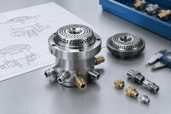
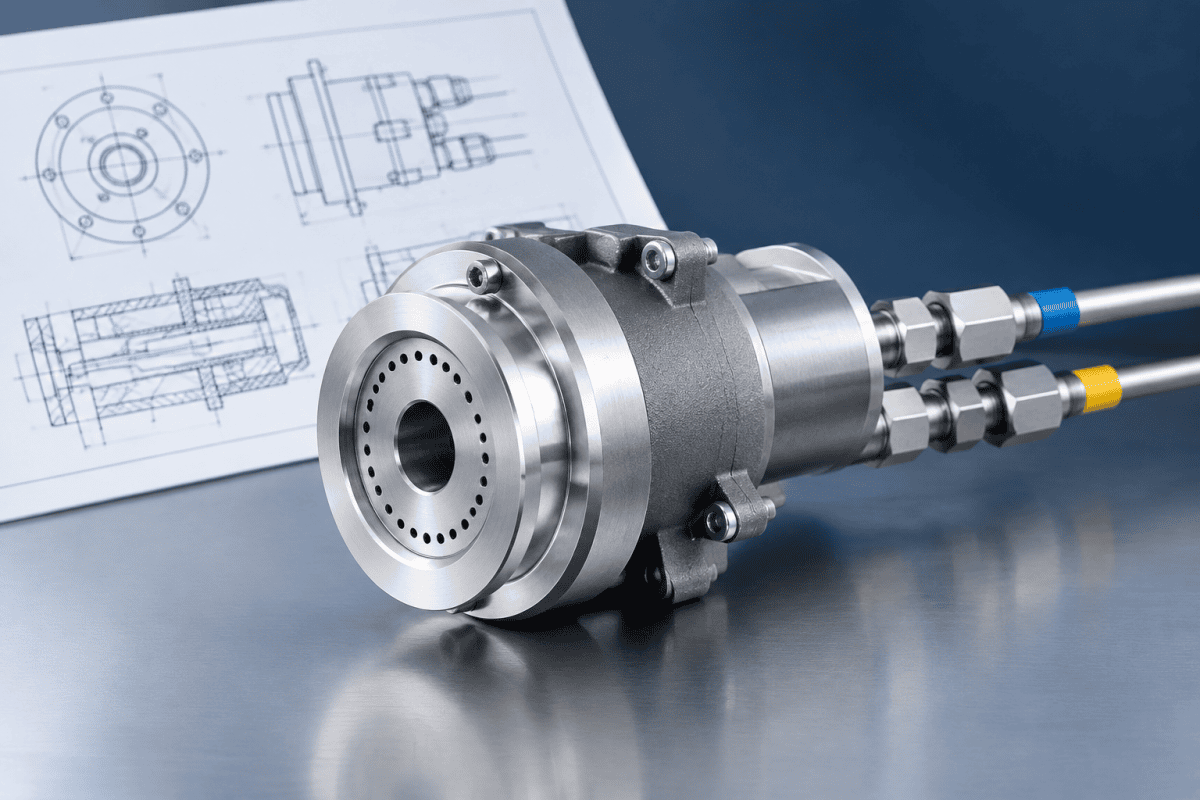
A burner drawing defines the physical part: overall envelope, nozzle pattern, channel diameters, faceplate surface, mounting features, and material callouts. The gas connection schedule defines how that part interfaces with the rest of the deposition system: which port receives which gas, thread or flange type, sealing method, and routing constraints.
A replacement can match the drawing perfectly and still perform poorly if a port is assigned to the wrong service, if a sealing face is altered, or if a fitting cannot physically reach its counterpart on the torch manifold. Conversely, correct port assignments mean little if nozzle concentricity or faceplate condition has drifted from the original design intent. Treat the two documents as a single specification package.
What to Verify on an OVD Burner Drawing
An OVD burner head component drawing should be detailed enough to manufacture from without verbal assumptions. When reviewing one for replacement purposes, check the following.
Nozzle Geometry and Channel Layout
- Nozzle count and arrangement: Verify the number of channels (typically fuel, oxygen, and one or more carrier or dopant lines) and their relative positions. Even a small change in spacing or ring diameter can affect flame structure and where soot deposits.
- Orifice diameters and tolerances: Note whether diameters are specified with tolerances and whether those tolerances are functional or simply shop-standard. Nozzle precision has a direct relationship to deposition stability, as discussed in this article on la précision des buses de brûleur et le rendement des préformes.
- Concentricity: Look for concentricity or runout callouts between the central channel and the outer rings. Missing callouts are a common gap in older drawings.
- État de surface : Faceplate finish affects soot adhesion and cleaning behavior. Rough surfaces tend to collect deposits differently than polished ones.
Materials and Construction
Material callouts should be read as functional requirements, not preferences. A burner head may use one alloy for the main body and a different material for the faceplate or nozzle inserts, depending on temperature exposure, thermal cycling, and the chemical environment. If the drawing does not identify which surfaces see the highest heat or which joints are brazed, welded, or mechanically sealed, ask before quoting. The broader logic of matching materials to burner duty is covered in this guide to custom burner sourcing and reverse engineering.
Mounting and Alignment Features
Record how the burner locates in the torch assembly: dowel pins, pilot diameters, keyed flanges, or clamp surfaces. These features set the burner’s position relative to the preform and to any auxiliary burners. If a replacement changes the locating method, the optical alignment may shift even if the flame itself behaves correctly.
What to Verify on the Gas Connection Schedule
Gas connections are where replacement projects most often stall. A burner that arrives with the correct nozzle pattern but incompatible port threads or sealing faces cannot be commissioned safely.
- Port-to-service mapping: Confirm which port carries fuel, oxygen, carrier gas, and any dopant or auxiliary line. Do not assume port order is consistent between drawing revisions.
- Thread and fitting standards: Identify thread type, size, and pitch, or whether connections use compression fittings, flanges, or face-seal designs. Metric and imperial mixes are a frequent source of mismatch. For reference on thread and fitting conventions, see the ASME codes and standards library.
- Sealing method: Note whether seals are metal-to-metal, gasket-based, or elastomer-based, and whether the sealing surface is part of the burner or the mating manifold.
- Routing and clearance: Check approach angles and available space around each port. A fitting that fits on a bench may not fit once the burner is installed in the lathe or deposition chamber.
- Purge or auxiliary lines: Some OVD installations use dedicated purge paths or auxiliary feeds. These must be identified so they are not accidentally capped or cross-connected.
Where oxygen distribution is handled by a separate manifold, compare the burner’s inlet requirements against that manifold’s outlets. The oxygen distribution manifold and auxiliary tail burner arrangement is one example where burner and manifold specifications must be reviewed as a pair.
Comparing an Existing Burner Against a Proposed Replacement
When a replacement is being sourced from a drawing rather than a catalog number, the most reliable approach is a structured dimensional and interface comparison.
- Lay out both drawings at the same scale. Overlay or compare envelope dimensions, nozzle positions, and mounting features. Do not rely on visual similarity alone.
- Build a port-by-port table. List each gas connection on the original and the proposed replacement: service, thread or fitting, sealing type, and position. Flag every difference.
- Check tolerances, not just nominal dimensions. A nozzle at the same nominal diameter but with a wider tolerance band may behave differently across a production run.
- Confirm material equivalence functionally. Two alloys with similar names can differ in thermal conductivity, oxidation resistance, or machinability. State the function each material must perform.
- Verify interface fit with the mating hardware. This includes the torch body, manifold, and any alignment fixture. Interface fit is often where a “drop-in” replacement turns out not to be one.
If the original drawing is incomplete or unavailable, reverse engineering from a retired burner is possible, but it should be treated as a measurement and documentation project rather than a quick copy. Worn nozzles and distorted sealing faces can mislead dimensional readings, so cleaned and inspected reference parts matter.
Inspection Points Before Installing a Replacement Head
Even a correctly specified burner head should be inspected on receipt. Useful checks include:
- Visual inspection of nozzle orifices for burrs, debris, or machining residue.
- Faceplate flatness and surface condition, particularly around the nozzle field.
- Thread condition and sealing face condition on every gas port.
- Dimensional spot checks against the drawing’s critical features.
- Cleanliness of internal channels, where accessible, to avoid introducing contamination into the gas path.
Soot accumulation and faceplate condition are routine maintenance concerns covered in more detail in this article on preventing silica soot clogging on OVD burner faceplates. Establishing a consistent incoming inspection routine makes it easier to distinguish a genuine OVD burner head replacement problem from an installation or process issue.
When a Drawing Alone Is Not Enough
Some replacement decisions require operating context that drawings do not capture. If a burner has been modified in service, if the process window has changed, or if the original part was itself a non-standard variant, a drawing-based quotation may need additional input. In those cases, supplying the following helps a supplier respond accurately:
- Marked-up drawings showing critical dimensions and tolerances.
- Photographs of the existing burner and its installed connections.
- A list of gas services and their connection types.
- Any known constraints on materials, cleaning, or assembly.
Custom and non-standard components can be produced from drawings or from measured samples through services d'usinage OEM/ODM, provided the interface requirements are documented clearly.
How Burner Design Affects Soot Deposition and Preform Yield
The reason drawings and gas schedules deserve this level of attention is that the burner is an active process component, not a passive fixture. Flame chemistry, velocity, and shape determine where silica particles form and how they deposit on the growing preform. A change in nozzle diameter, channel spacing, or gas velocity can shift the deposition profile enough to affect core-to-clad ratios and refractive index uniformity.
When evaluating an OVD burner head replacement, it helps to trace how each drawing feature influences the process:
- Nozzle diameter: Sets exit velocity for a given flow, which in turn affects flame length and particle residence time.
- Channel spacing: Influences mixing between fuel, oxygen, and carrier streams, and therefore flame temperature distribution.
- Faceplate condition: Soot buildup near the nozzle field can distort local flow and alter deposition symmetry.
- Port assignment: Incorrect routing changes the stoichiometry at the nozzle exit, even if total flows are unchanged.
Because these effects compound, a replacement that is dimensionally “close” is not necessarily process-equivalent. Documenting the functional role of each critical feature makes it easier to judge which drawing callouts are negotiable and which are not.
Dimensional and Tolerance Review in Practice
Drawing comparison is most effective when it follows a repeatable sequence. The steps below are suitable for both internal review and supplier communication.
- Establish the governing revision. Confirm which drawing revision reflects the currently installed burner, including any approved deviations.
- Identify critical-to-function dimensions. Mark nozzle diameters, concentricity, sealing faces, and mounting locations as critical; treat cosmetic or non-interface features as secondary.
- Record tolerance bands, not just nominal values. A dimension without a tolerance cannot be verified, and a wide tolerance on a critical feature is a risk.
- Cross-check against the gas schedule. Confirm that each documented port on the drawing corresponds to a defined service in the schedule.
- Note measurement uncertainty. When reverse engineering, record the instruments used and their resolution so future comparisons are meaningful.
Keeping this review in a single controlled document reduces the chance that a critical requirement is lost between engineering, procurement, and the machine shop.
Gas Connection Details That Most Often Cause Problems
In practice, a small number of connection issues account for most commissioning delays. Reviewing them explicitly before ordering an OVD burner head replacement saves significant rework.
- Sealing face geometry: A mismatch between a metal-to-metal seat and a gasket-style seat is not solved by tightening; it requires a corrected part.
- Thread compatibility: Similar-looking threads in different standards can engage partially and leak under pressure.
- Port orientation: A port rotated by a few degrees can interfere with adjacent fittings or obstruct access for torque tools.
- Material compatibility of fittings: Dissimilar metals at a connection can accelerate corrosion or galling over thermal cycles.
- Purge and vent paths: Omitting or capping a purge line can leave stagnant gas volumes that affect startup behavior.
Where any of these points is uncertain, resolving it at the drawing stage is far cheaper than resolving it during installation.
Documenting Requirements for a Supplier Quote
A clear requirements package speeds up quotation and reduces the risk of a non-conforming part. At minimum, include:
- The burner drawing with critical dimensions and tolerances highlighted.
- The gas connection schedule with port-to-service mapping.
- Material requirements stated by function, not just by alloy name.
- Any cleanliness, packaging, or traceability requirements.
- Operating conditions such as gas types, flow ranges, and thermal cycling.
When documentation is incomplete, state clearly what was measured, what was assumed, and what remains unknown. Suppliers can work with gaps if they are identified; they cannot work with gaps that are hidden.
Foire aux questions
Can I replace an OVD burner head using only the part number?
Only if the part number is tied to a complete and current drawing that matches your installed configuration. Part numbers alone rarely capture gas connection details, tolerance revisions, or in-service modifications. Always verify against the drawing and the connection schedule before an OVD burner head replacement is approved.
What if the gas connections on a replacement do not match my manifold?
Do not force a fit or adapt threads without engineering review. Mismatched sealing methods or thread standards can create leak paths or mechanical stress. Document the mismatch and either source a corrected burner or have an adapter evaluated by qualified personnel.
Are OVD and VAD burner heads interchangeable?
No. OVD and VAD burners differ in geometry, gas distribution, and process role, and MCVD uses different hardware again. Treat drawings and connection schedules as process-specific documents. A comparison of nozzle approaches across these processes is available in this OVD, VAD, and MCVD nozzle guide.
How do I know whether a dimensional difference matters?
Map each difference to a function: gas flow path, flame geometry, alignment, or sealing. Differences on non-functional surfaces are usually tolerable; differences in nozzle geometry, concentricity, or sealing faces deserve engineering review before installation.
How long does a typical OVD burner head replacement take to plan?
Timing depends on documentation quality. If drawings and gas schedules are current, quotation and review can proceed quickly. If reverse engineering is required, allow additional time for measurement, verification, and supplier confirmation before an OVD burner head replacement is scheduled.
Preparing a Replacement Request
A well-prepared request shortens the path from inquiry to quotation. Gather the original burner drawing, the gas connection schedule, a port-by-port service list, material requirements, and any photographs or measurements of the installed part. If the documentation is incomplete, note which dimensions were measured and which were assumed.
To discuss a specific replacement, you can contact our team with your drawings, dimensions, gas connection details, and operating conditions so the component requirements can be reviewed against your application.
Summary: Getting an OVD Burner Head Replacement Right
A successful OVD burner head replacement depends less on the part itself than on how thoroughly the drawing and the gas connection schedule are reconciled before the order is placed. Compare nozzle geometry, tolerances, materials, and mounting features against the original design. Then map every gas port by service, thread, sealing method, and physical clearance. Where the documentation is incomplete, document what was measured and what was assumed. An OVD burner head replacement should end with a complete interface record that the next maintenance cycle can reuse. Treated this way, an OVD burner head replacement becomes a controlled engineering change rather than a troubleshooting exercise.
