
Knowledge
Optical Fiber Bobbin Changeover Components: Custom Clamp and Cutter Parts
Oct
Optical fiber bobbin changeover is a short, high-stress window in the fiber draw and take-up cycle: the winding head decelerates, the fiber is captured and severed, the clamp releases the wound bobbin, and the next mandrel is brought into position. Every action depends on mechanical components that must locate, grip, and cut within a repeatable sequence. Because changeover happens hundreds or thousands of times per production period, small dimensional errors in clamps and cutter parts accumulate into reject bobbins, fiber breakage, and unplanned downtime. This article explains what these components do, how to inspect them, and how to prepare an accurate sourcing request.
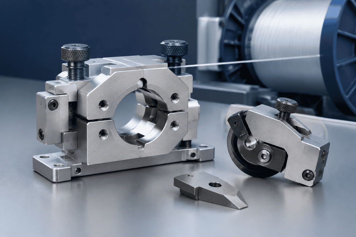
The topic sits firmly inside optical fiber bobbin changeover components, a category that includes the clamp jaw set, cutter blade and holder, guide elements, and the mounting interfaces that tie them to the winder. The most common assembly-level unit is the winder clamp cutter assembly, which combines fiber capture and severing in one replaceable group so that alignment between the two functions survives maintenance. When these parts are poorly matched to the machine, the entire take-up cycle becomes unpredictable, and a correctly specified set restores the repeatable sequence that production demands. Maintenance teams should treat the system as a whole rather than a set of individual parts, because each interface influences the next step in the cycle. A well-documented set of drawings also simplifies future rebuilds and reduces the risk of installing an incorrect substitute. Reliable optical fiber bobbin changeover components are therefore a key lever for winding yield and fiber protection.
Where Optical Fiber Bobbin Changeover Components Sit in the Changeover Sequence
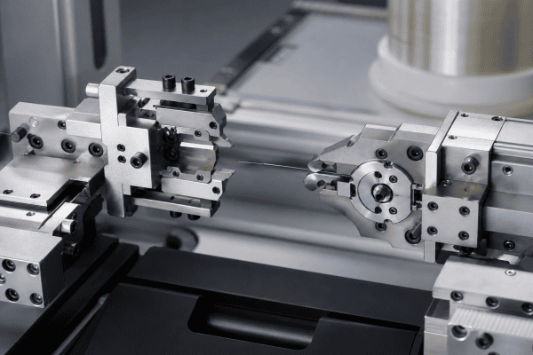
A take-up winder performs changeover in a fixed order:
- The traverse or laying head moves the fiber to a transfer position.
- A clamp or catcher captures the fiber against a defined surface.
- The cutter severs the fiber at a controlled point, leaving a tail for the next bobbin.
- The wound bobbin is released and indexed away.
- A new mandrel or tube is presented and engaged.
Each step depends on the geometry of the parts before it. If the clamp jaw does not close to the correct gap, the fiber is pinched unevenly and may slip during deceleration. If the cutter blade has lost edge sharpness or is mounted at the wrong angle, the severing action produces a ragged end that interferes with the next winding start. If the mounting faces are worn, both operations shift relative to the fiber path, and changeover quality becomes inconsistent across positions.
This sequence explains why these parts must be evaluated as a group: a clamp that grips well but a cutter that severs poorly still produces a failed changeover. The interaction between them is often more important than the performance of any single item. In practice, optical fiber bobbin changeover components that share a common datum should be replaced together to preserve the original geometry. Teams that track the parts as a matched set report fewer intermittent faults and faster root-cause analysis.
What Makes These Parts Different from Other Winder Components
Clamp and cutter parts are not passive guides. They are active contact elements with three distinguishing requirements:
- Repeatable positioning. The fiber path must be re-established to the same point at every changeover, so locating features such as dowel holes, shoulders, and datum faces matter more than the overall size of the part.
- Clean severing geometry. Cutter edge quality, rake angle, and the clearance between blade and counter-edge determine whether the fiber is cut cleanly or crushed.
- Wear and contamination tolerance. Coating residue, polymer dust, and silica debris accumulate on jaw faces and blade surfaces, gradually changing effective dimensions.
These requirements mean that a clamp or cutter part purchased as a generic substitute — matched only by approximate shape — will often function initially and then drift. The familiar consequence is a changeover that works on one position but fails intermittently on another, which is difficult to diagnose without dimensional checks. Optical fiber bobbin changeover components sourced without drawings tend to fail in exactly this pattern, because the critical locating dimensions are the first to be approximated.
Inspection Points Before Replacing a Clamp or Cutter Assembly
Before assuming a part is worn out, confirm the actual condition. The following checks separate probable causes from confirmed ones.
1. Clamp jaw condition
Look for flattened gripping surfaces, polished wear patches, embedded debris, and rounded entry edges. Measure the closed gap and compare it with the drawing value if one is available. A jaw that no longer closes to its original gap may grip inconsistently even when it appears intact.
2. Cutter edge and mounting angle
Inspect the blade under magnification rather than by eye alone. A slightly dulled edge can still sever fiber but will produce a rough end or require higher force. Check the blade seat for fretting, burrs, and contamination, since a blade sitting on debris will not hold its intended angle.
3. Locating features and datums
Dowel pins, shoulder contacts, and mounting holes are the reference points that preserve alignment. Wear at these features produces a shift that no amount of blade or jaw adjustment can correct. Check them for ovality, burrs, and seating marks outside the intended contact area.
4. Interface and actuator condition
Clamp and cutter parts interact with pneumatic cylinders, cams, springs, or linkages. Verify that the actuator stroke, return travel, and timing are consistent with equipment documentation. A part replaced because of a suspected geometry problem may actually be responding to a slow actuator or a worn linkage.
5. Fiber path confirmation
After any replacement, confirm that the fiber sits in the intended plane relative to the clamp and cutter. If the path is pulled or offset, the parts will wear asymmetrically and changeover reliability will decline again.
Material Selection Depends on Function, Not Category
Clamp and cutter parts are frequently grouped together in purchasing systems, but their material requirements differ. The correct choice depends on the component’s function, its temperature exposure, the chemical environment, and the engineering requirements of the machine builder.
- Clamp jaws need controlled friction, dimensional stability, and resistance to coating residue. Too hard a surface can mark or damage fiber; too soft a surface deforms and loses grip.
- Cutter blades need hardness and edge retention, with a geometry that severs rather than crushes.
- Holders, brackets, and bodies need stiffness and stable mounting faces, and may be produced in aluminum where mass and thermal behavior favor it.
It is not safe to infer a material from a broad product category or from a part’s appearance. Two visually similar clamp bodies may be specified in different alloys for different winder generations. The reliable approach is to work from the original drawing, a measured sample, or a clearly stated operating requirement. A guide such as the Nextrom VAD burner replacement parts sourcing guide covers similar material-selection logic for adjacent fiber production components, and the same discipline applies here: define the function first, then select the material. For broader context on fiber drawing and take-up, the Corning optical fiber overview provides background on the process these components support.
For components that are no longer supported by drawings, or that combine several functions in one body, OEM/ODM machining services allow production from a sample or a reconstructed drawing set. This is often the practical route for legacy winder positions where the original part number is unavailable. When optical fiber bobbin changeover components require reverse engineering, the drawing set should be rebuilt around functional dimensions rather than envelope shape, so that the replacement reproduces the original behavior instead of merely fitting the mounting space.
Sourcing a Replacement Clamp and Cutter Assembly
A useful quotation request is specific. Vague inquiries produce generic responses, and generic responses produce parts that need rework. Include the following where available:
- Assembly identification: machine type, winder position, and any legacy part number.
- Dimensional data: drawings, or measured dimensions of the existing part, including locating features and datum surfaces.
- Functional description: what the clamp grips, where the fiber is cut, and the intended changeover direction.
- Material and surface requirements: specified alloy, hardness, coating, or an operating condition that drives the choice.
- Interface details: mounting hole pattern, actuator connection, and any gas or vacuum ports.
- Quantity and replacement pattern: single spare, position set, or planned rebuild kit.
Photographs help, but they are not a substitute for dimensions. A photograph can confirm a general shape; it cannot confirm a closed gap, a blade angle, or a dowel position. Where a drawing exists, send it. Where it does not, a measured sample plus a description of the failure mode gives a machinist far more to work with. See the approved internal reference on take-up winder clamp replacement: dimensions and grip checks and the optical fiber winder clamp & cutter assembly product page for related dimensional guidance.
Common changeover symptoms and their likely origins
- Fiber slips during deceleration. Check clamp gap, jaw surface condition, and actuator force before replacing the jaw set.
- Ragged or crushed fiber end. Inspect cutter edge condition and blade seating; confirm the blade is at the specified angle.
- Changeover works on some positions but not others. Compare locating features and mounting faces across positions; this usually indicates a wear or alignment issue rather than a design fault.
- Progressive decline over weeks. Look for contamination buildup and fretting at datums, which change effective geometry gradually.
- Sudden failure after maintenance. Verify assembly orientation and seating; a part installed one step out of position can mimic a worn component.
Some of these symptoms overlap with burner-side and deposition-side issues that affect the fiber earlier in the process. If changeover problems appear alongside deposition variability, it is worth confirming that the upstream condition is stable, since burner concentricity and refractive index profile drift can change fiber characteristics in ways that later show up as handling problems at the winder. A systematic approach to troubleshooting optical fiber bobbin changeover components should always begin with the least invasive checks and move toward replacement only when dimensions confirm wear.
Maintaining Changeover Reliability Over Time
Clamp and cutter components respond well to a simple maintenance discipline:
- Keep jaw faces and blade seats clean; residue is a dimensional change, not just a cosmetic issue.
- Record the changeover interval and note when rejects begin to cluster, so wear trends become visible before failure.
- Replace clamp and cutter elements as a matched set when they share a common datum, rather than one at a time.
- Retain at least one known-good sample of each critical part for dimensional comparison.
Where several winder positions use similar but not identical parts, labeling and storage discipline prevents incorrect installation. This is a common and easily overlooked cause of intermittent changeover faults. A maintenance log that records the condition of optical fiber bobbin changeover components at each service interval turns scattered observations into a usable wear history. Over time, that history shows which parts fail first and whether the cause is mechanical wear, contamination, or an upstream process change.
FAQ
Can a clamp or cutter part be replaced without a drawing?
Yes, in many cases, provided the existing part can be measured accurately and the key functional dimensions are identified. Locating features, closed gap, and blade angle matter more than overall envelope dimensions. Reverse engineering from a sample is a normal approach for legacy components, but it should be done by someone who understands which dimensions carry the function.
Is the winder clamp cutter assembly interchangeable between machine types?
Not automatically. Assemblies that look similar may differ in mounting pattern, actuator interface, fiber path position, or blade geometry. Compatibility has to be verified against drawings, dimensions, connection points, materials, and the specific application rather than assumed from appearance or product family.
How do I know whether the problem is the clamp, the cutter, or the actuator?
Isolate the functions. Test the clamp grip independently of the cut, inspect the cutter edge and seat separately from the jaw faces, and verify actuator stroke and timing against equipment documentation. This separates a confirmed dimensional or wear problem from a control or timing issue that a new part will not solve.
What information speeds up a quotation for custom changeover parts?
Drawings or measured dimensions, the operating function of each feature, material or surface requirements, interface details, and quantity. A description of the failure mode is also useful, because it often reveals which dimensions are most critical to reproduce.
Next Step
If a changeover position is producing intermittent rejects or you are rebuilding a legacy winder, the fastest path to a usable part is a clear specification. Send your drawings, measured dimensions, material requirements, and a short description of the operating conditions through our quotation request page, and the team can review whether a standard optical fiber equipment part fits or whether a custom-machined replacement is the better route. A complete specification for optical fiber bobbin changeover components should always include the failure mode, because that single detail often determines which dimensions of those optical fiber bobbin changeover components are critical to reproduce.
