
Знание
Сборочные детали резака намоточного устройства для оптического волокна: Руководство по спецификациям замены
Окт
When a fiber draw or take-up line starts producing inconsistent cut lengths, ragged fiber ends, or clamp marks on the wound package, the cause is usually found in the winder clamp and cutter assembly—not in the draw process itself. Specifying детали режущего узла для намотчика оптического волокна correctly is therefore a maintenance and yield issue, not just a purchasing formality. This guide explains how these assemblies work, what to measure before ordering replacements, which material and geometry decisions matter most, and how to prepare a drawing package that lets a supplier quote or manufacture custom components without guesswork.
Choosing optical fiber winder cutter assembly parts is not a simple catalog exercise. It starts with understanding the assembly as a system, then working backward to the individual components that wear, shift, or degrade over time. This article covers the key specifications, inspection logic, and sourcing steps that lead to a reliable replacement.
What Optical Fiber Winder Cutter Assembly Parts Do in the Winder
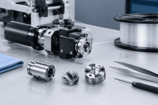
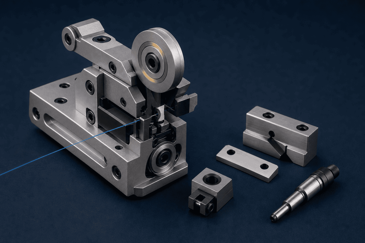
A fiber winder clamp and cutter assembly performs three jobs at the end of a winding cycle: it grips the fiber or the package so it does not move, it severs the fiber cleanly at a defined point, and it releases in a way that does not damage the fiber surface or disturb the package. On many machines these functions are combined in a single mechanism, with a clamp jaw, a cutting blade or edge, an actuator, and mounting hardware moving in a timed sequence.
Because the cut and the clamp happen together, a problem in one function often shows up as a symptom in the other. A dull blade can cause tension spikes that the clamp then translates into package distortion. A worn clamp pad can let the fiber shift slightly during the cut, producing an angled or frayed end even when the blade is sharp. This interaction is the main reason the зажима намотчика оптического волокна и режущего узла should be evaluated as a system rather than as individual wear parts.
For a closer look at how the clamp itself is dimensioned and grip-checked, the guide to take-up winder clamp replacement covers the measurement points that matter most. Together, the clamp and cutter determine whether every cycle ends with a clean, repeatable cut or with a defect that has to be trimmed or scrapped. That is why optical fiber winder cutter assembly parts deserve the same engineering attention as the deposition and draw components upstream.
Symptoms That Point to Cutter or Clamp Wear
Before ordering parts, confirm that the winder assembly is actually the source of the problem. Some symptoms are strong indicators; others overlap with fiber handling or tension-control issues elsewhere on the line.
- Ragged, angled, or crushed fiber ends. Typically points to blade wear, blade alignment, or insufficient clamp force allowing movement during the cut. Verify by inspecting the cut face under magnification and checking whether the end angle changes when clamp pressure is adjusted.
- Inconsistent cut lengths. Often a timing or actuation issue rather than a blade issue. Check actuator stroke, sensor triggering, and mechanical play before replacing cutting components.
- Clamp marks or surface damage on the package. Usually clamp pad wear, contamination, or excessive clamp force. Confirm by swapping or cleaning pads and re-running a test package.
- Fiber slip during the cut. Can come from worn pads, contaminated clamp surfaces, or misalignment between the clamp and blade. Verify by checking whether slip occurs at a consistent point in the cycle.
- Blade chipping or edge deformation. Usually mechanical interference, contamination, or a blade material that is mismatched to the fiber and coating being cut.
Treat each of these as a possible cause, not a diagnosis. A single replacement part will only solve the problem if the underlying cause is the worn component and not, for example, a drifting actuator, a loose mount, or a control timing change. When cut quality problems persist across multiple packages, the pattern of the defect usually points to whether the fault sits in the clamp, the blade, or the actuation sequence.
Specifications to Confirm Before Ordering Replacements
Cutter and clamp components are not interchangeable across winder designs, and they should not be assumed to be interchangeable across machine generations from the same builder. The following specification set is the minimum needed for a reliable replacement or a custom quotation.
Dimensional and Mounting Data
- Blade length, width, thickness, edge angle, and cutting geometry
- Clamp jaw length, contact width, radius, and pad thickness
- Mounting hole pattern, hole diameter, and counterbore dimensions
- Pivot or bearing bore diameters and shaft fits
- Actuator interface dimensions, including stroke and mounting thread
- Overall assembly envelope and clearances to adjacent components
Where drawings are unavailable, reverse engineering from the worn part is possible, but it must be done dimensionally rather than by visual match. A part that looks identical may differ in blade edge angle or pad durometer, and those differences affect cut quality.
Optical Fiber Winder Cutter Assembly Parts that are visually similar but dimensionally different are one of the most common sources of premature failure after a rebuild. The clamp and cutter assembly product page is a useful reference for how the complete unit is configured when a replacement is being planned.
Material Selection Factors
Blade and clamp materials should be chosen according to function, not by category. For cutting edges, the relevant factors are hardness, edge retention, toughness, and corrosion resistance against any contaminants present in the environment. For clamp pads, the relevant factors are compressibility, surface friction, wear resistance, and whether the pad material will mark or contaminate the fiber coating.
Two common mistakes appear in replacement sourcing. The first is choosing the hardest available blade material without considering toughness; a very hard edge can chip under shock loading. The second is replacing a polymer clamp pad with a harder material to extend life, which can transfer damage to the fiber instead.
Both decisions should be based on the actual cutting and clamping conditions and the fiber type being handled. When optical fiber winder cutter assembly parts are sourced without a clear material rationale, the replacement often trades one failure mode for another.
Surface Finish and Edge Quality
For cutting edges, the finish near the edge and the consistency of the edge angle are often more important than the bulk material. A blade that meets hardness specifications but has an inconsistent edge will produce variable cut quality. For clamp faces, surface roughness affects grip and marking. Both characteristics should be specified on the drawing rather than left to supplier interpretation.
Actuator Interface and Timing
The actuator interface is frequently the weakest link in a replacement specification because it is treated as a secondary detail. Stroke length, mounting thread, rod diameter, and the position of the end-of-travel sensing all affect how the clamp and blade sequence against the winding cycle. If the actuator interface is not measured with the same care as the cutting edge, the new components may fit but mistime the cut.
For optical fiber winder cutter assembly parts to perform as intended, the actuator interface dimensions should be recorded alongside the blade and clamp dimensions rather than treated as a separate project.
Replacement Versus Custom Cutter Components
Standard replacement parts make sense when the original component is still available and the machine is unmodified. Custom cutter components become the practical option when the original part is obsolete, when a redesign has changed the interface, when lead times for OEM parts disrupt maintenance, or when the user wants to improve a known weak point such as pad life or edge retention.
When going the custom route, keep the following in mind:
- Provide a complete drawing or a fully measured sample. Partial dimensions force the supplier to guess, and guesses become fit problems.
- State the function of each feature. A chamfer that exists for assembly clearance is specified differently from one that controls fiber position.
- Identify critical versus non-critical dimensions. Not every dimension needs the same tolerance, and over-tolerancing raises cost without improving function.
- Describe the operating environment. Temperature, cleaning methods, and exposure to coatings or solvents all influence material choice.
- Specify the interface, not just the part. The component must fit the actuator, mount, and adjacent hardware as an assembly.
For a broader view of how custom-machined replacements are qualified across preform equipment, the guide to Corning preform equipment parts sourcing outlines the supplier qualification steps that apply equally to winder components.
Machines from different builders also impose different constraints, and the notes on поиск запчастей для оборудования для преформ Sumitomo Electric show how interface details change between platforms. A similar review of SG Controls preform equipment replacement parts is useful when a custom RFQ is being prepared for a legacy machine. When the requirement is specifically a lathe or carriage component, the guidance on SG Controls MCVD lathe spare parts explains how holders and carriages are dimensioned for replacement. Heat-related assemblies follow the same logic, as described in the notes on Nextrom MCVD heating burner components and the drawing-based approach to Запасные части для горелки Nextrom VAD.
Inspection and Maintenance Logic
A short, repeatable inspection routine prevents most unplanned cutter failures. The goal is to detect wear before it affects product quality, not to replace parts on a fixed schedule that may be too early or too late.
- Inspect the cutting edge for chips, rolled edges, or contamination. Use magnification; edge damage is often invisible at normal viewing scale.
- Check clamp pad condition for compression set, glazing, embedding of debris, or chemical swelling.
- Verify alignment between the clamp, the blade, and the fiber path. Misalignment is a common cause of angled cuts that is mistaken for blade wear.
- Check actuator stroke and mounting tightness. Loose mounts and shortened strokes change cut timing and clamp force.
- Record cut quality against part condition so that replacement intervals are based on evidence rather than habit.
Where cut quality changes are accompanied by broader deposition or preform issues, it is worth separating winder-related defects from upstream causes. The guide to take-up winder clamp replacement can help confirm whether a quality shift originates in the winder or earlier in the process.
Inspection records should be tied to the specific optical fiber winder cutter assembly parts installed, including batch or drawing revision. Without that traceability, it is difficult to tell whether a change in cut quality follows a particular supplier, a particular material lot, or a genuine wear trend. Recording the part revision at each inspection also makes it easier to justify a design change when a repeated failure mode appears. Well-documented optical fiber winder cutter assembly parts reduce the guesswork in every maintenance decision.
Подготовка запроса на закупку
A clear request shortens quotation time and reduces the risk of receiving a part that fits but does not perform. Include the following in the inquiry:
- Machine type and the position of the assembly on the winder
- Drawings, sketches, or measured dimensions of the existing component
- Material requirements, including any restrictions on coatings or lubricants
- Operating conditions: fiber type, coating type, cycle rate, and cleaning regime
- Quantity, including whether a single replacement or a small batch is needed
- Any known failure mode that the replacement is intended to address
Photographs of the installed assembly are useful supporting information, but they do not replace dimensions. If a drawing does not exist, a measured sample with clearly marked reference surfaces is the next best input. When the source drawing is genuinely unavailable, a first-article inspection report should be requested so that the delivered optical fiber winder cutter assembly parts can be checked against the sample before they are installed on a production line.
It also helps to state which dimensions are wear-critical. On a blade, the edge angle and thickness near the tip usually control cut quality, while the mounting holes control fit. On a clamp, the contact radius and pad thickness usually control grip, while the jaw length controls clearance. Separating wear-critical from fit-critical dimensions lets the supplier allocate tolerance where it actually affects performance.
Advances and Standards in Cutting and Clamping
Blade geometry and edge preparation for industrial cutting have been studied extensively, and much of that work applies directly to fiber winder components. The National Institute of Standards and Technology publishes metrology and materials references that are useful when specifying edge quality and dimensional tolerances for precision components. Reviewing dimensional-metrology guidance before writing a drawing helps ensure that the tolerances requested can actually be measured and verified by the supplier.
For fiber-specific handling requirements, the published standards and technical notes from organizations such as the ITU Telecommunication Standardization Sector provide useful context on fiber geometry and handling, which in turn informs how much clamp force and edge sharpness a given fiber type will tolerate. These references do not replace machine drawings, but they help frame the operating limits that a replacement component must respect.
Common Specification Mistakes
Several recurring mistakes lengthen lead times and produce parts that fail early. The most common is specifying by appearance rather than by measurement, which works only when the original part is fully dimensioned. The second is omitting the actuator interface, which causes timing problems that are later misdiagnosed as blade wear. The third is selecting a material by reputation rather than by function, which can improve one property while degrading another.
A fourth mistake is treating the clamp and cutter as independent items when they are ordered together. Because their functions interact, a change in one component can require a compensating change in the other. When optical fiber winder cutter assembly parts are specified as a set, the supplier can check the interaction rather than only the individual dimensions.
A fifth mistake is failing to record the operating conditions, which leaves the supplier to assume a fiber type, coating, and cycle rate that may not match the actual line. Any of these oversights can turn a straightforward optical fiber winder cutter assembly parts order into a costly rework cycle.
Часто задаваемые вопросы
Can a winder cutter assembly be replaced with a part from a different machine model?
Only after verifying dimensions, mounting pattern, actuator interface, and blade geometry against the actual machine. Similar appearance is not evidence of compatibility, and the assembly should be confirmed against drawings and operating requirements before installation.
How do I decide between resharpening a blade and replacing it?
Resharpening is viable when the blade geometry can be restored within specification and the material has enough remaining section. Replacement is the better choice when the edge angle cannot be reproduced, when the blade has chipped, or when the material has been degraded by heat or corrosion.
What information is needed to quote a custom cutter component?
A drawing or measured dimensions, the material or performance requirements, the interface dimensions, and the operating conditions. Where the original drawing is missing, a sample plus marked reference features allows the component to be reverse engineered accurately.
Do clamp pads and cutting blades need to be replaced together?
Not necessarily, but they should be inspected together. Because clamp condition affects cut quality, replacing a blade while leaving a worn pad in place can reproduce the original defect. Base the decision on measured condition rather than on paired replacement as a rule.
Следующий шаг
If you are sourcing replacement or custom winder clamp and cutter components, send your drawings, dimensions, material requirements, and operating conditions to request a quotation. Providing the interface dimensions and the function of each feature allows the part to be reviewed against your assembly rather than matched by appearance alone. A complete specification package is the fastest route to reliable optical fiber winder cutter assembly parts, and it reduces the risk of a second order to correct a fit or performance problem.
